 info@unicomposite.com


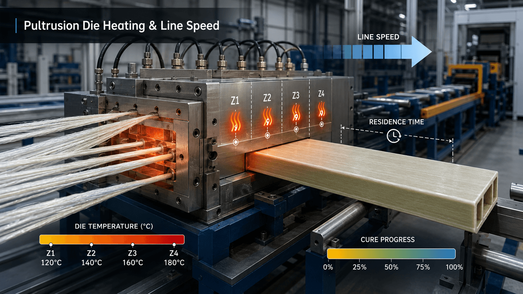
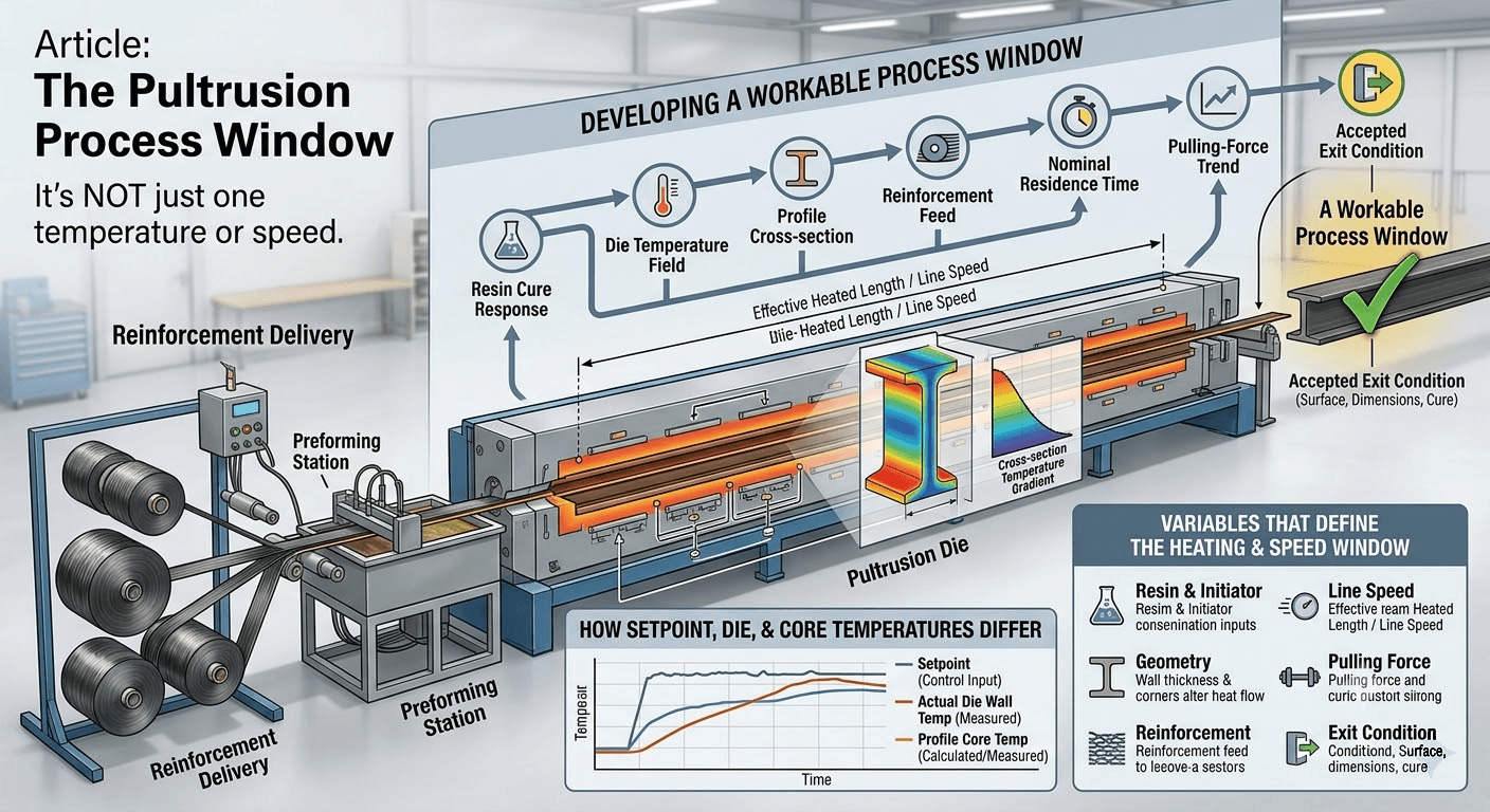
Pultrusion die heating cannot be reduced to one recommended temperature or one standard line speed. A workable process window must connect the resin’s cure response, the actual temperature field inside the die, the profile cross-section, reinforcement delivery, nominal residence time, pulling-force trend and accepted exit condition.
Changing only a heater setpoint or pull speed can move the cure reaction to a different position inside the die. That change may solve one symptom while creating another. The reliable approach is to establish a measured baseline, change one controlled factor at a time and verify the result against the same material, profile and acceptance criteria.
pultrusion die heating line speec
Why There Is No Universal Pultrusion Die Temperature
Temperature starts the discussion, but it does not define the process by itself. The same die setpoint can produce different internal temperature and cure histories when the resin chemistry, initiator package, reinforcement, wall thickness, cavity geometry or line speed changes.
Research on pultrusion heat transfer treats die temperature, line speed, cure kinetics, reaction heat and changing material properties as coupled variables, not independent settings.1 A broader review of pultrusion simulation reaches the same conclusion: resin flow, heat transfer, reaction, pulling force and stress development belong to one connected process model.2
This leads to three practical rules:
- A controller setpoint is not proof of the actual die-wall temperature.
- Die-wall temperature is not proof of the profile-core temperature or degree of cure.
- A setting that works for one resin, section or production line is an unverified starting hypothesis for another.
The Variables That Define the Heating and Speed Window
Before changing the process, identify which inputs stayed constant and which changed.
| Input or signal | Why it changes the process window | What to record or verify |
|---|---|---|
| Resin and initiator system | Determines reaction rate, gel behavior, exotherm and required thermal history | Current supplier data, batch, mix ratio, storage and available cure analysis |
| Profile geometry | Wall thickness, corners, hollows and mass distribution alter heat flow from the die wall to the core | Controlled drawing, wall sections and critical dimensions |
| Reinforcement package | Fiber amount, mats, fabrics and preforming affect compaction, resin distribution and friction | Material configuration, tension and preformer setup |
| Die and heating arrangement | Heated length, heater placement, contact and thermal losses affect the temperature field | Zone setpoints, actual response, sensor location and warm-up state |
| Line speed | Changes nominal residence time and the moving material’s thermal history | Actual speed synchronized with temperature and force records |
| Pulling force | Responds to compaction, resin state, friction, buildup and cure location | Trend and variability, not only a single reading |
| Exit condition | Shows whether the combined window produces an acceptable profile | Surface, dimensions and the project’s cure or performance acceptance method |
The purpose of this input list is not to collect more data than necessary. It prevents a temperature adjustment from being credited for a result that was actually caused by a resin, material-feed or setup change.
Nominal Residence Time Is Useful—but It Is Not a Cure Specification
A simple first check is:
Nominal residence time = effective heated length ÷ line speed
Effective heated length means the portion of the tooling used as the thermal basis for the comparison. It should not automatically be assumed to equal the die’s total physical length.
Use consistent units in the calculation. If effective heated length is entered in metres and line speed in metres per minute, the resulting nominal residence time is expressed in minutes.
If line speed increases while the effective heated length remains unchanged, nominal residence time decreases. This is useful for comparing trials on the same tooling, but it does not prove that cure is complete. The profile heats from its boundaries while the resin reacts and releases heat; the center and surface may therefore follow different temperature histories.
Studies of pultrusion temperature fields show that pull speed can change both die-wall and centerline temperature behavior, with the effect also depending on section size.3 Use nominal residence time as a comparison variable, then verify actual temperature response and the accepted exit condition.
How Die Temperature Changes Cure Location
Increasing temperature generally accelerates thermoset reaction and can move the exothermic or high-reaction region toward the die entrance. That does not mean the highest available temperature is the best setting.
An industrial vinyl ester study found that higher test temperatures advanced cure and increased the measured degree of cure. However, the highest mechanical performance occurred at an intermediate test temperature rather than at the hottest tested condition.4 Those experimental temperatures and results belong to that resin system and test setup; they are evidence of the relationship, not transferable production settings.
Moving the reaction too far downstream can leave insufficient cure at the exit. Moving it too far upstream can increase the risk of early gelation, friction or buildup before the reinforcement package has passed through the intended forming and consolidation sequence. The target is a controlled cure progression that produces the required exit condition without unstable pulling load or thermal damage.
Why Setpoint, Die Temperature and Profile Temperature Differ
A temperature controller reports the value measured at its sensor. It does not automatically describe every point in the die or profile.
A pultrusion temperature setpoint is a control input, not a direct measurement of the complete thermal history experienced by the resin.
Differences can arise from:
- heater placement and contact;
- sensor location and installation;
- heat loss to supports and surrounding equipment;
- incoming material temperature;
- profile cross-section and thermal properties;
- resin reaction heat;
- line speed;
- start-up versus steady-state operation.
Multi-heater modeling has shown that the longitudinal heating profile can be optimized to improve cure uniformity across a section.5 That finding supports the use of purposeful zone design, but it does not prescribe a universal number of zones or a standard temperature difference between them.
Treat each sensor as one observation in a thermal system. When the process result and controller display disagree, verify the sensor, heater response and measurement location before rewriting the production recipe.
Why Start-Up and Steady-State Thermal Conditions Differ
A die that has reached controller setpoints without material moving through it is not necessarily at the same thermal condition as a die during continuous production. Incoming reinforcement and resin absorb heat, the resin releases reaction heat, and the surrounding structure exchanges heat with the die.
Research that included the die block and heater arrangement found that transient start-up and steady-state operation require different thermal analysis.6 For this reason, a useful trial record separates:
- warm-up completion;
- material entry and initial pull;
- transition toward steady operation;
- stable production baseline;
- planned speed or temperature changes;
- shutdown or interruption conditions.
Do not compare a start-up observation with a steady-state target without marking the operating phase.
A Controlled Method for Developing the Process Window
A pultrusion temperature-speed window should be developed through controlled trials, not by selecting two independent settings.
1. Establish the material basis
Record the exact resin system, initiator or hardener information, fillers, internal release system and reinforcement configuration. Use current resin-supplier data and available thermal analysis rather than copying a temperature from a different formulation.
ASTM D5028 is a test method for evaluating curing properties of pultrusion resins by thermal analysis.7 It can support material characterization, but it does not specify a universal die temperature or line speed.
2. Define what success means
Choose acceptance evidence before the trial. Depending on the project, this may include dimensional results, surface condition, a documented cure assessment, mechanical testing or another approved inspection method. Appearance alone may not prove that the profile core has followed the required cure history.
3. Record a synchronized baseline
Use the last accepted run when available. At minimum, synchronize:
- resin and reinforcement configuration;
- zone setpoints and available actual-temperature readings;
- line speed;
- pulling-force trend;
- defect or observation location along the profile;
- dimensions and exit condition;
- time from start-up to the observation.
4. Test one supported hypothesis
Change one controlled factor while holding the others as stable as practical. If temperature and speed are changed together, the result cannot show which change moved the cure location or pulling load.
5. Verify the complete response
Do not accept a trial only because one symptom disappeared. Check whether the adjustment changed:
- exit cure evidence;
- surface and dimensions;
- pulling-force level and variability;
- buildup location;
- temperature stability;
- repeatability over an appropriate production interval.
6. Document the accepted window
Record the material, tooling, setup, operating phase and acceptance method with the settings. A number without this context is not a reusable process window.
the pultrusionprocess window
Temperature and Speed Troubleshooting Matrix
Use the table as an investigation order, not as an automatic correction recipe.
| Observed signal | Competing explanations | First checks | Controlled next step |
|---|---|---|---|
| Soft, tacky or otherwise unacceptable exit condition | Insufficient thermal history; speed too high for the current system; heater or sensor response; changed resin; thick-section gradient | Confirm material identity, actual speed, available temperature response and where the condition occurs across the section | Restore the last accepted baseline or test one approved speed/temperature change, then verify cure by the project’s acceptance method |
| Blisters or void-related surface disruption | Cure and gas evolution occurring in an unsuitable location; moisture; impregnation; entrained air; resin or material change | Map defect position, compare temperature and speed history, inspect material preparation and wet-out evidence | Separate thermal-window evidence from material and impregnation causes before adjusting heat |
| Pulling force rises gradually | Resin buildup; cure moving upstream; reinforcement compaction; surface friction; contamination; speed or temperature drift | Save the force trend; inspect entry, preforming and buildup; compare actual temperature and material records | Correct one confirmed setup or contamination issue, or test one supported thermal hypothesis |
| Pulling force oscillates or spikes | Reinforcement feed variation; preformer misalignment; intermittent buildup; sensor/control cycling; pulling-system issue | Correlate force with zone response, material feed and defect spacing | Stabilize the identified source and repeat under the same baseline |
| Surface appears acceptable but core evidence is unsatisfactory | Cross-section temperature gradient; insufficient residence time; material-specific cure response | Compare wall sections, core-sensitive acceptance evidence and line speed | Review the thermal path and effective heated length; do not rely on surface appearance alone |
| Process drifts after a stable start | Heater or sensor response; heat loss; material batch; ambient or feed change; accumulating contamination | Mark when drift began and compare synchronized trends | Verify instrumentation and changed inputs before modifying the recipe |
| Reaction or buildup appears too close to the entrance | Excessive early heat; speed reduction without thermal rebalance; resin or initiator change; fiber compaction | Check material batch, actual speed, entry-zone response and buildup location | Return to a known safe baseline and move only one approved variable |
Experimental work on specific vinyl ester profiles found that die temperature, pulling speed, die length and thickness affected blister formation together.8 This is why a visible defect should start an investigation, not trigger an automatic temperature correction.
Pulling Force Is a Trend, Not a Root-Cause Label
Pulling force helps identify when the process has changed, but it cannot identify the cause on its own. Experimental research connects pull force with temperature, resin conversion, compaction, friction and reinforcement configuration.9 More recent injection-pultrusion work also compared core-temperature and cure development with measured pulling force.10
Interpret force together with:
- where the defect appears;
- whether the force changed suddenly or gradually;
- temperature and speed trends;
- resin and reinforcement changes;
- preforming and entry condition;
- die-surface condition and buildup.
For a broader symptom-led investigation, use our guide to pultrusion mold failure causes and corrective action.
Information to Preserve Before Changing the Die or Heating System
Before requesting a tooling or heating review, prepare:
- the controlled profile drawing and critical tolerances;
- resin and cure information from the current supplier;
- reinforcement layout and preforming arrangement;
- die drawing or available heated-length and sensor-location information;
- temperature, speed and pulling-force trends;
- photographs and mapped defect locations;
- the last accepted baseline;
- the acceptance method and failed result;
- a list of recent material, setup, maintenance or equipment changes.
Heating performance is also linked to cavity geometry, section distribution and tooling architecture. See Pultrusion Die Design: Geometry, Materials & Surface Finish for the separate design task.
When to Stop the Trial and Escalate
Stop and follow the site’s safety and equipment procedures when there is uncontrolled heating, damaged electrical equipment, an unexplained hot spot, smoke or degradation, abnormal tool movement, reinforcement breakage, rapidly increasing pulling force or an unsafe profile condition.
Do not bypass interlocks, access energized heaters, move sensors, grind the die or change electrical components as a content-guided troubleshooting step. Those actions require authorized personnel and a documented engineering procedure.
Frequently Asked Questions
What temperature should a pultrusion die run at?
There is no universal value. The initial range must come from the actual resin system and available cure characterization, then be validated with the profile geometry, reinforcement, die arrangement, line speed, measured response and acceptance criteria.
Can line speed be increased when die temperature is increased?
Possibly, but the two changes should not be treated as an automatic pair. Higher temperature can accelerate cure, while higher speed shortens nominal residence time and changes the thermal field. Use controlled trials and verify core-sensitive cure evidence, dimensions, surface condition and pulling-force stability.
Does high pulling force mean the die temperature is wrong?
Not necessarily. Temperature and cure location can affect pulling force, but so can reinforcement compaction, resin state, friction, buildup, preforming, surface damage and the pulling system. Preserve the trend and check competing causes before changing heat.
Discuss Pultrusion Tooling Inputs
Explore our pultrusion molds and tooling page, or send us your profile drawing, critical tolerances, resin information, reinforcement plan, target production conditions and acceptance requirements for a project discussion. The applicable tooling scope, technical inputs, trial requirements and commercial terms can then be documented during project review and quotation. If heating or sensing requirements have already been defined, include them with the project information.
References
- Batch, G. L., and Macosko, C. W. “Heat transfer and cure in pultrusion: Model and experimental verification.” AIChE Journal 39, no. 7 (1993): 1228–1241. https://doi.org/10.1002/aic.690390713
- Safonov, A. A., Carlone, P., and Akhatov, I. “Mathematical simulation of pultrusion processes: A review.” Composite Structures 184 (2018): 153–177. https://doi.org/10.1016/j.compstruct.2017.09.093
- Chachad, Y. R., Roux, J. A., Vaughan, J. G., and Arafat, E. S. “Effects of Pull Speed on Die Wall Temperatures for Flat Composites of Various Sizes.” Journal of Reinforced Plastics and Composites 15, no. 7 (1996). https://doi.org/10.1177/073168449601500706
- Chaparala, S. A. C., et al. “Characterisation of Curing of Vinyl Ester Resin in an Industrial Pultrusion Process: Influence of Die Temperature.” Polymers 15, no. 18 (2023): 3808. https://doi.org/10.3390/polym15183808
- Li, J., Joshi, S. C., and Lam, Y. C. “Curing optimization for pultruded composite sections.” Composites Science and Technology 62, no. 3 (2002): 457–467. https://doi.org/10.1016/S0266-3538(02)00018-0
- Ding, Z., Li, S., and Lee, L. J. “Influence of heat transfer and curing on the quality of pultruded composites. II: Modeling and simulation.” Polymer Composites 23, no. 5 (2002): 957–969. https://doi.org/10.1002/pc.10493
- ASTM International. “ASTM D5028-25, Standard Test Method for Curing Properties of Pultrusion Resins by Thermal Analysis.” https://store.astm.org/d5028-25.html
- Li, S., Ding, Z., Xu, L., Lee, L. J., and Engelen, H. “Influence of heat transfer and curing on the quality of pultruded composites. I: Experimental.” Polymer Composites 23, no. 5 (2002): 947–956. https://doi.org/10.1002/pc.10492
- Mukherji, A., and Njuguna, J. “An assessment on effect of process parameters on pull force during pultrusion.” The International Journal of Advanced Manufacturing Technology 121 (2022): 3419–3438. https://doi.org/10.1007/s00170-022-09221-0
- Tucci, F., Esperto, V., Pasquino, G., and Carlone, P. “Injection Pultrusion of Glass-Reinforced Epoxy: Cure Kinetics, Rheology, and Force Analysis.” Polymers 16, no. 12 (2024): 1642. https://doi.org/10.3390/polym16121642


