 info@unicomposite.com


Introduction
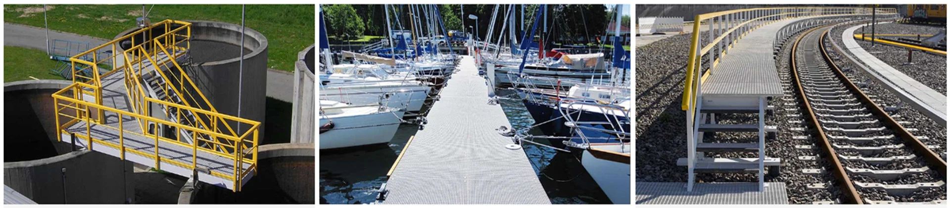
FRP handrail systems are specified for industrial platforms, chemical plants, and offshore facilities because they eliminate the corrosion and conductivity issues that plague metallic handrail installations. But the performance advantages assumed at specification time depend on correct installation — incorrect post spacing, wrong fastener material, or unverified anchor patterns can compromise a system that would otherwise deliver 20+ years of maintenance-free service.
This guide walks installation teams through the six-step process for assembling FRP handrail systems, the structural load requirements that govern post spacing and rail dimensions, and the two installation mistakes that cause most premature failures.
frp handrail installation guide
Before You Start: Tools and Components Required
FRP handrail installation does not require specialized equipment beyond standard trade tools — but the fastener and bit selection matters more than for metallic handrail systems.
Standard Tool List
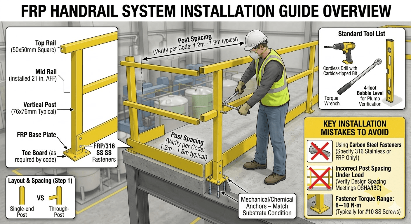
A typical FRP handrail installation crew works with: a cordless drill with carbide-tipped or diamond-coated bits (high-speed steel bits dull rapidly and produce rough holes in FRP), a torque wrench calibrated to the fastener specification, a 4-foot bubble level for plumb verification, measuring tape, a non-marking rubber mallet, and personal protective equipment including a dust mask or respirator for cutting operations. FRP cutting produces fine respirable dust, so industrial dust extraction — manufacturer-recommended and aligned with OSHA general-duty respiratory protection requirements — is the appropriate setup for any on-site trimming.
FRP Handrail System Components Overview
A standard FRP handrail system consists of seven component categories: top rail (typically 42 mm diameter round or 50×50 mm square section), mid rail (matching profile, installed at 21 inches AFF for OSHA compliance), vertical posts (76×76 mm typical for industrial applications), base plates with pre-drilled anchor holes, rail connectors (fixed or articulating depending on stair geometry), end caps, and toe boards where required by code.
Confirm the component bill of materials against the supplier’s drawing before beginning installation — particularly the distinction between single-end posts (used at stair landings and termination points) and through-posts (used at intermediate locations). This distinction is the single most common cause of mid-installation parts shortages on FRP handrail projects, because the two post types look visually similar but are not interchangeable in the connection hardware they accept.
FRP Handrail Installation: Step-by-Step Process
Before the step sequence, one practical observation from a recent industrial mezzanine retrofit illustrates why the process below emphasizes substrate verification: the installation crew arrived expecting standard mechanical anchors per the project drawing, but the existing concrete substrate showed surface spalling at multiple post locations. The change to chemical anchors with deeper embedment was made mid-installation, but doing so under field conditions consumed half a day of schedule and required engineering review of the anchor design. The lesson applies broadly: confirm substrate condition during pre-installation walkthrough, not at the drilling stage.
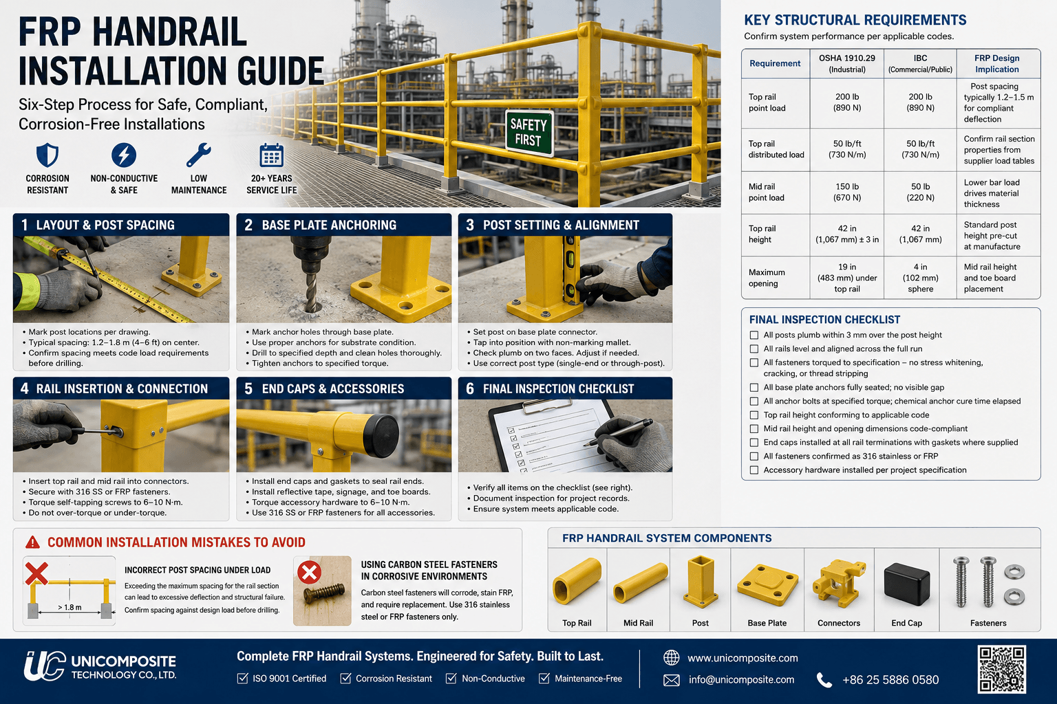
Step 1 — Layout and Post Spacing
Mark post locations on the substrate using the supplier’s drawing as reference. For standard industrial platforms, post spacing typically ranges from 1.2 m to 1.8 m (4 to 6 feet) on center, with the maximum spacing determined by the rail section’s load capacity under the applicable code’s point load requirement. Closer spacing increases system load capacity but also increases material and labor cost — confirm the design spacing meets OSHA 1910.29 or IBC requirements for the project’s load case before drilling anchor holes.
Step 2 — Base Plate Anchoring
Set each base plate at its marked location and mark the anchor bolt positions through the plate’s pre-drilled holes. Anchor specification should differentiate by substrate condition. For 4,000+ psi concrete in good condition, mechanical wedge anchors with 75 mm embedment typically suffice. For older concrete with surface spalling, unknown compressive strength, or visible cracking, chemical or epoxy anchors with 100–125 mm embedment and a substrate pull-out test are the defensible specification.
Drill anchor holes to the depth specified by the anchor manufacturer. Clean the holes thoroughly — dust residue is the most common cause of anchor pull-out failures in FRP installations because the FRP base plate cannot tolerate the retorquing that steel plates allow when an anchor begins to loosen. For steel substrates, through-bolting with backing plates is the standard connection.
Step 3 — Post Setting and Alignment
Place each post over its corresponding base plate connector and tap into seated position with a non-marking rubber mallet. Check vertical alignment with a level on two perpendicular faces before securing connection hardware. Posts that go in slightly out of plumb are extremely difficult to correct after rail installation begins — verify plumb at this stage rather than after.
For stair installations, confirm the post is appropriate for its location: single-end (terminal) posts at landings and stair top/bottom; through-posts at intermediate locations along the run.
Step 4 — Rail Insertion and Connection Hardware
Insert the top rail and mid rail into their corresponding post connectors. Most FRP handrail systems use friction-fit or slip-fit connections at the posts, secured with self-tapping screws or through-bolts depending on the manufacturer’s design. Torque self-tapping fasteners to the supplier’s specification — typically 6–10 N·m for #10 stainless screws into FRP. Over- torquing strips the threads in the FRP; under-torquing allows rail movement under lateral load.
Use 316 stainless steel or FRP fasteners exclusively. Carbon steel fasteners will corrode at the contact zone in any environment that justified specifying FRP in the first place — the visible failure mode is rust streaking on the rail surface, which appears within 6–12 months in coastal, chemical-exposed, or continuously humid environments. In dry interior installations, the timeline extends substantially, but the failure mode is identical and the maintenance cycle that FRP was specified to eliminate returns through the fastener material.
Step 5 — End Cap, Gasket, and Accessory Hardware Installation
Install end caps on all rail terminations to prevent moisture ingress into the hollow rail sections. Where the supplier provides EPDM or silicone gaskets at the end cap interface, install them per the supplier specification — moisture that enters through unsealed end caps does not damage the FRP itself but can freeze in cold climates and progressively loosen the cap connection over multiple winter cycles.
For high-visibility safety applications, install reflective tape and signage brackets at this stage. Reflective tape placement should comply with ANSI Z535.1 color standards for safety markings where applicable, and any through-bolted accessory hardware should be torqued to the same 6–10 N·m range as primary rail fasteners. Confirm all accessory hardware uses 316 stainless or FRP fasteners — accessory components are the most commonly overlooked source of carbon-steel-fastener contamination in otherwise correctly specified installations.
Step 6 — Final Inspection Checklist
Before turning the installation over for project closeout, verify each of the following items and document the inspection for the project record:
- ☐ All posts plumb within 3 mm over the post height
- ☐ All rails level and aligned across the full run; visible deflection within supplier-specified limits
- ☐ All fasteners torqued to specification — no visible stress whitening, cracking, or thread stripping at the FRP interface
- ☐ All base plate anchors fully seated; no visible gap between base plate and substrate
- ☐ All anchor bolts at specified torque; chemical anchor cure time elapsed per manufacturer specification
- ☐ Top rail height conforming to applicable code (typically 42 inches per OSHA 1910.29; verify against project specification)
- ☐ Mid rail height and opening dimensions code-compliant
- ☐ End caps installed at all rail terminations with gaskets where supplied
- ☐ All fasteners visible at inspection confirmed as 316 stainless or FRP
- ☐ Accessory hardware (reflective tape, signage, toe boards) installed per project specification
Key Structural Requirements for FRP Handrail Systems
The structural load requirements that govern FRP handrail design align with the recommendations published in NAAMM’s Pipe Railing Systems Manual, which serves as a common reference baseline that FRP handrail suppliers are asked to match in their load tables for North American projects. The table below summarizes the requirements that procurement teams should confirm against project conditions:
| Requirement | OSHA 1910.29 (Industrial) | IBC (Commercial/Public) | FRP Design Implication |
|---|---|---|---|
| Top rail point load | 200 lb (890 N) in any direction | 200 lb (890 N) | Post spacing typically 1.2–1.5 m for compliant deflection |
| Top rail distributed load | 50 lb/ft (730 N/m) | 50 lb/ft (730 N/m) | Confirm rail section properties from supplier load tables |
| Mid rail point load | 150 lb (670 N) | 50 lb (220 N) | Lower bar load drives material thickness specification |
| Top rail height | 42 in (1,067 mm) ± 3 in | 42 in (1,067 mm) | Standard post height pre-cut at manufacture |
| Maximum opening | 19 in (483 mm) under top rail | 4 in (102 mm) sphere (commercial) | Mid rail height and toe board placement |
In addition to the load requirements above, procurement teams should request material property documentation against ASTM D635 (flame spread for FRP), ASTM D790 (flexural properties), and ASTM D2583 (Barcol hardness as a cure quality indicator). These three standards together verify that the supplied material matches the structural assumptions in the load tables. Always request a supplier-issued span-and-load calculation for the specific rail section and post spacing on your project — manufacturer catalog ratings based on assumed spacing may not match your actual layout.
frp handrail system installation guide overview
Common Installation Mistakes to Avoid
Incorrect Post Spacing Under Load
The single most common FRP handrail installation error is post spacing exceeding what the rail section can support under the applicable code’s point load requirement. A 1.8 m spacing may be acceptable for a lightly-loaded walkway but inadequate for a stairway subject to evacuation loading. Confirm spacing against the design load case before drilling anchors, not after.
Using Carbon Steel Fasteners in Corrosive Environments
The second most common error is mixing carbon steel fasteners with FRP components in installations that specified FRP precisely because of corrosion concerns. Carbon steel screws and bolts will corrode at the FRP interface, streak the rail surface with rust within 6–12 months in corrosive service, and require replacement on the same maintenance cycle that FRP was specified to eliminate. Specify 316 stainless steel or FRP fasteners across the entire system — including accessory hardware that is often procured separately from the primary handrail components.
Conclusion
Correct FRP handrail installation depends on five decisions that cannot be corrected after the system is in service:
- Verify design post spacing against the applicable load code before drilling anchor holes — OSHA 1910.29 for industrial sites, IBC for commercial or public installations. For non-standard configurations, request a project-specific span-and-load calculation from the supplier.
- Specify 316 stainless or FRP fasteners across the entire system. Carbon steel hardware in any FRP installation defeats the corrosion specification that justified FRP in the first place — including accessory hardware procured separately from primary components.
- Match anchor specification to substrate condition. Mechanical anchors for sound concrete; chemical anchors with pull-out testing for spalled, cracked, or unknown-strength substrates. Confirm during pre-installation walkthrough, not at the drilling stage.
- Torque fasteners to supplier specification. Over-torquing strips FRP threads; under-torquing allows rail movement and accelerates connection wear. The 6–10 N·m range typical for #10 stainless screws into FRP is a starting reference, not a substitute for the supplier’s published spec.
- For non-standard installations, route the design through a structural engineer’s review before procurement. Custom stair geometries, unusual load cases, or retrofits into structurally compromised substrates require engineering judgment that catalog selection alone cannot replace. The review belongs in the design phase, not after the field issue surfaces.
Unicomposite Technology Co., Ltd. supplies complete FRP handrail systems — including posts, rails, base plates, connectors, and the 316 stainless fastener kits that this guide identifies as the most common installation specification error — as a single coordinated package. Engineering support for custom post spacing, non-standard stair geometries, and project-specific load requirements is available at the design stage from the ISO 9001-certified manufacturing facility in Nanjing.
[Contact Unicomposite for FRP handrail system components, installation hardware kits, and project-specific engineering support →]


