 info@unicomposite.com


Quick Answer
The main advantages of pultrusion are continuous production, efficient use of aligned reinforcement and repeatable constant-section profiles. Its main limitations are directional properties, fixed cross-sectional geometry, profile-specific tooling and the need for controlled impregnation and cure. This guide explains the advantages and disadvantages of the FRP pultrusion process and when another composite manufacturing route may be a better fit. Pultrusion is usually a strong fit when the profile, load path, production volume and tooling investment support a continuous process. Start with those factors and the project’s acceptance requirements before choosing the process.
pultrusion process advantages limitations
What Is the Pultrusion Process?
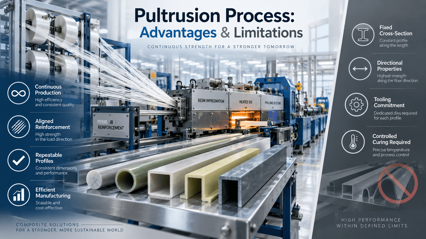
In conventional thermoset pultrusion, dry fiber reinforcements or textile forms are guided and impregnated with resin, shaped through a preforming system, and pulled through a heated die. Heat causes the resin matrix to cure or crosslink, creating a continuous profile that is hauled off and cut to the required length, with downstream handling or coiling where the product and line allow it. This sequence is described by Fraunhofer IGCV and the U.S. Environmental Protection Agency’s reinforced-plastics process review. [1][2]
The die defines the profile’s cross-section. That makes pultrusion fundamentally different from processes that form each part independently: the process is most efficient when the same section can be produced continuously and the reinforcement can be placed to carry the intended loads.
The Main Advantages of Pultrusion
1. Continuous production for repeatable profiles
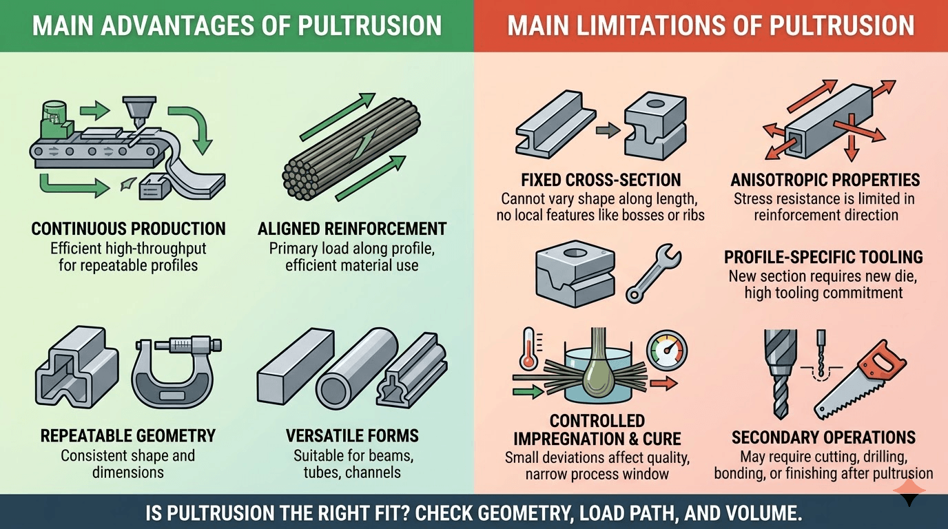
Once the reinforcement path, resin system, die, heating, pulling and cutting conditions are established, pultrusion can produce long lengths without stopping after every part. The continuous sequence can reduce repeated handling and support consistent output for medium- and high-volume requirements. A recent review describes pultrusion as a highly automated, high-throughput composite process, while Fraunhofer IGCV highlights economic material consumption and consistent quality as process advantages. [1][3]
The practical question is not simply whether a line can run continuously. It is whether the required profile, order volume, changeover plan and inspection method justify the tooling and process-development work.
2. Efficient use of aligned reinforcement
Pultrusion places a substantial portion of the reinforcement along the profile length. That is useful when the primary load path is longitudinal, such as tension, bending or stiffness along a rod, beam, channel or tube. The reinforcement plan still needs to include transverse or surface-oriented materials when the application has shear, impact, bearing, handling or connection loads.
The resulting properties are directional. A high value in the length direction does not automatically describe transverse strength, impact resistance, joint performance or behavior around holes and cut-outs. Those requirements must be checked against the laminate architecture and the project’s acceptance criteria.
3. Repeatable geometry and surface formation
The die, guides and process settings establish the profile shape while the material passes continuously through the forming and curing stages. This can support repeatable dimensions and surface formation when the die condition, reinforcement delivery, resin behavior and thermal process remain within the validated window.
Repeatability is therefore a process-control outcome, not a property that can be guaranteed from the word “pultrusion” alone. The control plan should identify which dimensions, surface features and defects are checked, how often they are measured, and what action is taken when a trend moves outside the acceptance limit.
4. Multiple Profile Forms and Material-System Options
Within the constraint of a substantially constant cross-section, pultrusion can produce solid, hollow and open profiles, provided the geometry can be formed and pulled through the tooling. Common reinforcement forms include rovings, mats, fabrics and other textile products. Resin and reinforcement selection are application-specific: chemical exposure, temperature, electrical requirements, fire requirements, moisture, UV exposure, structural loads and joining details can all change the appropriate system.
This flexibility is valuable for design, but it also increases the need for early definition of the profile, resin, reinforcement layout and acceptance requirements. A shape that looks simple in a drawing may still require a different preforming or impregnation approach.
5. Application-Dependent Material Benefits
FRP systems made by pultrusion are often considered for applications where low mass, corrosion resistance, electrical insulation or reduced maintenance can matter. These are properties and outcomes of the selected composite system and design, not guarantees created by the pultrusion process itself. The comparison must use the actual resin, reinforcement, exposure conditions, load spectrum, joints, supports and inspection requirements.
For that reason, a fair comparison with steel, aluminum, wood or another composite process should include both initial cost and the expected maintenance, replacement and installation implications. A generic statement such as “FRP always lasts longer” is not a valid engineering decision rule.
The Main Limitations of Pultrusion
1. The profile must remain suitable for continuous pulling
The die establishes a repeated cross-section along the production direction. Large changes in section, local bosses, transverse ribs, holes, variable wall features or complex three-dimensional geometry generally require secondary operations, inserts, a different process or a combination of processes.
The U.S. EPA review identifies the inability to vary cross-sectional characteristics along the length as a primary pultrusion limitation. [2] Before selecting pultrusion, mark every feature on the drawing that changes along the length and classify it as:
- formed in the die;
- introduced through reinforcement or an insert;
- machined after pultrusion; or
- better produced by another process.
2. Properties are anisotropic
Continuous reinforcement aligned with the profile creates a strong directional bias. This is an advantage for axial load paths, but a limitation when the design depends on transverse strength, interlaminar performance, impact tolerance, holes, fasteners, bonded joints or concentrated bearing loads. The EPA review describes stress resistance as being limited primarily in the reinforcement direction. [2]
The design review should therefore record the principal load directions, connection details and damage scenarios. If the profile will be drilled, bolted, clamped, bonded or cut, evaluate the local load transfer rather than selecting the material from axial properties alone.
3. Tooling is a commitment
The die and associated preforming or guidance equipment are designed around a specific profile. A new section or a substantial geometry change may require new or modified tooling. This creates a higher front-end commitment than a process that uses a flexible mold for one-off shapes.
Tooling cost is only one part of the decision. The review should also consider the expected volume, number of variants, changeover time, profile scrap during development, inspection effort and the cost of secondary machining. For a short run or rapidly changing geometry, compare pultrusion with alternative routes using tooling, development, changeover, scrap, secondary machining and expected total volume rather than unit production cost alone.
4. Impregnation and cure must stay within a usable process window
Fiber wet-out, resin viscosity, preforming pressure, die heating, pulling force and cure development interact. Fraunhofer IGCV notes that even small deviations in process parameters or hardware can deteriorate profile quality or interrupt continuous pultrusion. [1]
The relevant control question is not “What temperature or speed should every line use?” There is no universal setting that applies to every resin, reinforcement package, die and profile. Instead, establish a process window from the resin data, reinforcement architecture, die design, thermal response, pulling-force trend and accepted-profile inspection results.
5. Secondary operations and inspection may still be necessary
Cutting, drilling, bonding, machining, end finishing, inserts and connection preparation can be required after the continuous profile exits the die. Each operation can create local damage, expose reinforcement, change dimensions or alter the load path.
The production plan should define the finished-part condition, not only the as-pultruded profile. Include cut length, hole position, end condition, surface acceptance, dimensional checks and any destructive or non-destructive verification required by the project.
Pultrusion Fit: A Practical Decision Matrix
| Project condition | Pultrusion fit | Why it matters | What to verify before commitment |
|---|---|---|---|
| Long parts with one repeated section | Strong candidate | Continuous forming can reduce repeated handling | Section stability, length plan and cut-off method |
| Medium or high repeat volume | Often easier to justify economically | Tooling and setup effort can be spread across more parts | Volume forecast, variants and changeover plan |
| Main loads run along the profile | Often favorable | Aligned reinforcement supports the primary load path | Transverse, bearing, impact and joint requirements |
| Section changes along the length | Limited | The die forms a repeated cross-section | Secondary operations, inserts or another process |
| Highly complex 3D geometry | Usually limited | Continuous pulling and die access become difficult | Alternative process or hybrid manufacturing route |
| Small quantity with frequent design changes | Requires a closer tooling and economic review | Tooling commitment can dominate the economics | Prototype route, flexible tooling and development plan |
| Corrosive or electrically sensitive environment | Potentially favorable | FRP may reduce corrosion or conductivity concerns | Resin, exposure, fire, electrical and maintenance requirements |
| Tight dimensional or surface requirements | Possible, but process-dependent | Die condition and process control affect results | Tolerances, measurement method, trend limits and acceptance sample |
A High-Level Comparison with Other Composite Manufacturing Routes
There is no universal “best” composite process. The correct comparison starts with geometry, volume, reinforcement direction and the amount of secondary work.
| Decision factor | Pultrusion | Flexible molding or lay-up | Compression or injection molding |
|---|---|---|---|
| Best starting geometry | Long, repeated cross-section | One-off or more variable shapes | Discrete parts with defined mold cycles |
| Production pattern | Continuous | Batch or part-by-part | Repeated discrete cycles |
| Reinforcement layout | Strongly process-directional unless additional reinforcement is designed in | More freedom to place local reinforcement | Depends on charge, mold and flow design |
| Tooling decision | Profile-specific die and guides | More adaptable mold for some shapes | Dedicated mold and press or injection equipment |
| Typical review risk | Cure, wet-out, pulling force and section stability | Labor variation and consolidation | Fill, pressure, cycle and mold-flow behavior |
The table is a screening framework, not a substitute for a design review. A hybrid route may be the best answer: pultrude the constant profile, then machine, bond, overmold or assemble the features that cannot be formed continuously.
advantages and disadvantages of pultrusion
A Six-Point Pultrusion Selection Checklist
Before requesting tooling or approving a process route, prepare the following information:
- Profile definition — cross-section drawing, overall dimensions, wall features, allowable radii and features that change along the length.
- Load path — axial, bending, shear, bearing, impact, connection and handling loads, including the locations of holes, fasteners or bonded joints.
- Material inputs — reinforcement forms, resin family, surface requirements, inserts, fillers and the exposure conditions that drive the selection.
- Production plan — target quantity, part length, variants, changeover expectations, cut lengths and acceptable development scrap.
- Quality plan — critical dimensions, surface criteria, visual defects, sampling frequency, test methods and acceptance rules.
- Commercial and project constraints — tooling budget, required documents, packaging, delivery assumptions and the information a supplier must include in the quotation.
This checklist turns a general “Can this be pultruded?” question into a reviewable production decision. It also exposes missing inputs early, before a die or reinforcement package is locked in.
Common Selection Errors
Treating axial strength as a complete material specification
Axial strength may be important, but it does not answer how a profile behaves at holes, joints, transverse loads, impact or long-term exposure. Define the load cases and connection details before comparing material options.
Choosing a process from unit cost alone
Pultrusion can be efficient at the right volume, but tooling, development, inspection, secondary operations and design changes affect total cost. Compare the full project route rather than a manufacturing-rate estimate alone.
Using a generic temperature or speed as a production recipe
Thermal response and pulling conditions depend on the resin, reinforcement, die, geometry and line. Use a controlled development plan and accepted-profile measurements instead of copying a number from an unrelated line.
Ignoring the final connection and finishing method
A profile may be easy to pull but difficult to drill, bolt, bond, seal or assemble. Bring the connection and finishing details into the process review at the same time as the cross-section.
Treating a standard section as automatically suitable
Two profiles with the same outer shape can require different reinforcement layouts, resin systems, surface treatments or acceptance criteria. Confirm the application inputs instead of selecting a section from appearance alone.
Related Technical Resources
For a concise process overview, see our pultrusion process guide. For tooling inputs and geometry decisions, review pultrusion die design. If the project depends on thermal and pulling-force interactions, see pultrusion mold temperature and speed.
Conclusion
Pultrusion is most compelling when the project needs a repeatable, long profile and the reinforcement can be aligned with the main load path. Its trade-offs are equally important: the section must remain suitable for continuous forming, properties are directional, tooling is profile-specific, and impregnation and cure require controlled development.
If the project includes a new or revised die, explore our pultrusion molds and tooling. Send us your profile drawing, critical tolerances, resin information, reinforcement plan, target production conditions and acceptance requirements. We will use those inputs to define the tooling discussion and quotation scope, identify missing project information and set the product and document requirements that need to be addressed during review.
References
[1] Fraunhofer IGCV — Pultrusion. Process description, process advantages, material/process variables and troubleshooting context.
[2] U.S. Environmental Protection Agency — Economic Impact Analysis of the Final Reinforced Plastics NESHAP, section 2.1.2.1, pp. 2-14 to 2-15 in the PDF. Pultrusion process description, reinforcement direction and constant-cross-section limitations.
[3] Liu, X. et al., “Cost-efficient, automated, and sustainable composite profile manufacture: A review of the state of the art, innovations, and future of pultrusion technologies,” Composites Part B: Engineering, 2022, 110135. https://doi.org/10.1016/j.compositesb.2022.110135


