 info@unicomposite.com


Introduction
Field drilling FRP fiberglass profiles is one of the most consistently underestimated installation challenges in composite structural projects. The material is brittle, glass fiber dust is a respiratory hazard, standard drill bits dull within minutes, and the most common outcome — hole-edge delamination — is invisible until the connection fails under load. By that point, the profiles are installed, the platform is commissioned, and the failure is a maintenance problem rather than a procurement decision.
Ordering pre-drilled profiles eliminates every one of these problems before the material reaches the job site. This guide explains why FRP profile drilling requires different tooling and technique than metal drilling, what factory CNC machining delivers that field drilling cannot, which applications benefit most from pre-drilled profiles, and exactly what information to provide when specifying profiles with holes to your dimensions.
Unicomposite Technology Co., Ltd offers CNC automated hole-drilling as a standard secondary processing service alongside its pultruded profile production at its 18,000 m² facility in Nanjing, China. Unicomposite’s CNC drilling service was developed in direct response to a consistent pattern in customer inquiries: buyers who ordered FRP profiles and then contacted Unicomposite’s technical team about field drilling problems were describing the same three failure modes — delamination, exit face spalling, and bit dulling — regardless of their geographic location or installation type. The most common underlying cause was feed rate: field crews drilling at metal fabrication speeds rather than the lower feed rates that composite tooling requires. Factory CNC programming eliminates operator feed rate judgment from the process entirely.

pre drilled frp profiles
1. Why Drilling FRP Profiles Is Not Like Drilling Metal
1.1 The Material Properties That Make FRP Drilling Difficult
FRP is a composite of glass fiber reinforcement and a cured resin matrix — two materials with fundamentally different mechanical properties locked together in a structure that behaves as neither one independently. This composite character is precisely what creates the drilling challenge that metal fabrication experience does not prepare installation crews to handle.
Brittleness is the primary issue. FRP’s elongation-at-break runs approximately 1–2%, compared to 10–25% for mild steel. When a drill bit enters steel, the surrounding material deforms plastically, supporting the hole perimeter as the bit advances. When a drill bit enters FRP, the surrounding material cannot deform — it fractures at the fiber-matrix interface if the cutting force exceeds what the brittle composite can absorb.
Heat generation compounds the problem. FRP’s low thermal conductivity — approximately 0.3 W/m·K versus 50 W/m·K for carbon steel — prevents heat from dissipating away from the drill tip through the material. Heat builds up locally, melting the resin matrix at the hole perimeter and fusing glass fiber dust into the drill flutes. Standard HSS drill bits typically dull after 3–5 holes in glass fiber composite under typical field drilling conditions — 10–12 mm diameter, 6–8 mm wall thickness, dry drilling without coolant; smaller diameters and thinner walls extend this range, while larger diameters and thicker walls shorten it significantly.
The dust hazard is the third dimension that metal drilling does not present. Glass fiber cutting dust consists of respirable particulate that bypasses N95 filtration — P100 respiratory protection is the correct specification, and field drilling generates this particulate in a working environment that rarely has the enclosed dust extraction that factory machining provides.
1.2 The Three Failure Modes of Incorrect FRP Drilling
Hole-edge delamination is the most common failure mode and the most dangerous because it is invisible from the surface. Excessive feed rate or incorrect drill geometry causes fiber-matrix separation at the hole perimeter during drilling. The hole appears dimensionally correct on visual inspection, but the bearing area available to the fastener bolt is reduced — by up to 40% in severe cases based on cross-sectional inspection of failed FRP bolted connections, a figure consistent with ASTM D953 bearing strength test data showing the relationship between delamination depth and load-bearing width reduction. The connection performs below its structural design assumption without any indication that this has occurred until load testing or failure.
Surface spalling on the exit face occurs when the drill pushes material outward on breakthrough rather than cutting through it cleanly. The exit face fractures in a cone shape around the hole, producing a ragged edge larger than the nominal drill diameter. This condition is visible and immediately apparent, but repairing it requires filling and re-drilling — an on-site operation on an installed component that is difficult to execute without full removal.
Thermal resin damage produces a heat-affected zone around the hole perimeter where the resin matrix has softened under drilling heat and re-solidified at reduced cross-link density. This condition is not detectable visually and does not show up in standard dimensional inspection — it manifests as reduced fastener pull-through resistance under axial load, which only appears in destructive testing or field failure.
2. Factory CNC Drilling vs. On-Site Field Drilling
2.1 How CNC Automated Drilling Works for FRP Profiles
CNC punching and drilling for FRP profiles begins with fixturing the profile on a precision work table, positioning it against reference datums that establish the coordinate system for all hole locations. A pre-programmed drilling path then delivers each hole at the specified RPM, feed rate, and drilling depth — parameters optimized for the specific profile wall thickness, resin system, and hole diameter rather than estimated by an operator.
Carbide-tipped or diamond-coated drill tooling maintains consistent cutting geometry across an entire production batch. Positional accuracy from CNC drilling reaches ±0.5 mm for hole center location, referenced to ISO 2768-m medium precision tolerance class — the standard applicable to structural bolted connections in composite profiles. Field drilling with hand-marked positions and a handheld drill typically achieves ±2–3 mm, an error that accumulates as alignment mismatch when multiple bolt patterns must register across a bolted assembly.
Batch consistency is the characteristic that matters most for procurement managers specifying FRP profiles for large installations. CNC programming guarantees that hole position, diameter, and depth are identical across every profile in the production run. When 200 fence rail sections must bolt to 200 post positions, the tolerance stack-up from consistent factory drilling is manageable; the tolerance stack-up from 200 individually field-drilled holes is not.
2.2 What CNC Drilling Delivers That Field Drilling Cannot
Clean, burr-free holes are the most immediately visible difference between factory CNC machining and field drilling. CNC tooling at controlled feed rates produces a smooth hole perimeter without frayed fiber projections. Field drilling at incorrect feed rates leaves burrs that require manual removal with a round file before fastener installation, and the burr removal process itself introduces surface damage at the hole boundary that initiates corrosion in aggressive service environments.
Integrated dust extraction is the safety difference that factory machining provides and field drilling cannot replicate without dedicated ventilation equipment. Factory CNC machining operates with enclosed dust collection that captures glass fiber particulate at the source. Field drilling generates airborne particulate that contaminates adjacent surfaces, requires full PPE for any workers in the vicinity, and creates cleanup obligations that extend installation time.
Post-drilling edge sealing as a factory step is the corrosion protection difference. Pre-drilled profiles can receive hole-edge resin sealing as part of the factory finishing process, restoring the corrosion barrier at the cut surface before the profile ships. Field-drilled holes require the installation crew to apply compatible resin sealant on site — a step that is correctly specified in the installation document and correctly omitted in field practice at a rate that creates the premature corrosion failures described in Section 1.
The table below compares factory CNC drilling and on-site field drilling across the parameters most relevant to structural installation quality:
| Parameter | Factory CNC Drilling | On-Site Field Drilling |
|---|---|---|
| Hole position tolerance | ±0.5 mm (ISO 2768-m) | ±2–3 mm (cumulative) |
| Hole diameter consistency | ±0.1 mm across batch | ±0.5–1.0 mm (operator-dependent) |
| Hole-edge delamination risk | Low (controlled feed rate and tooling) | High (incorrect speed/feed common) |
| Dust control | Enclosed extraction at source | Airborne — full PPE required |
| Post-drill edge sealing | Available as factory step | Field step — frequently omitted |
| Tooling cost per hole | Amortized across production run | Per-hole HSS bit cost + frequent replacement |
| Batch consistency | Identical across all profiles | Variable — operator and condition dependent |
3. Machining Capabilities for FRP Pultruded Profiles
3.1 Hole Drilling: Diameters, Patterns, and Profile Types
Standard through-hole drilling covers diameters from 5 mm to 50 mm in pultruded profiles. Countersunk and counterbored configurations are available for flush-fastener applications where the fastener head must sit at or below the profile surface — common in handrail systems and transport applications where projecting fastener heads create snagging or aesthetic concerns.
Hole patterns include single holes, bolt circle patterns, linear bolt rows, and fully asymmetric custom layouts per dimensioned drawing. Provide hole center coordinates referenced to the profile end face and to a consistent datum edge — this reference system eliminates the ambiguity that verbal position descriptions create for asymmetric cross-sections.
Compatible profile types cover all standard pultruded cross-sections: square tube, round tube, I-beam, channel, angle, flat bar, and solid rod. The governing constraint for hole position is minimum hole-to-edge distance — the standard minimum is 1.5× hole diameter from the nearest profile edge; for high-load bolted connections where bearing strength governs the joint design, 2× hole diameter provides more reliable bearing performance. Buyers can specify profiles, resin system, length, and hole pattern in a single order — no secondary fabrication vendor, no job-site drilling equipment, no glass fiber dust in the installation environment.
3.2 Additional Secondary Processing Options
Cut-to-length service delivers profiles cut to exact specified length with end-face squareness held to ±1 mm. In Unicomposite’s order history, cut-to-length is the most frequently combined service with hole drilling — buyers who specify hole patterns consistently also specify profile lengths, because the same drawing that locates holes also defines the overall profile dimension. Receiving profiles cut and drilled to a single drawing eliminates two separate fabrication steps from the installation site.
Miter and angle cutting produces end-face cuts at specified angles for corner connections, junction framing, and rafter-to-purlin joints. Maximum miter angle is typically ±45° from square; steeper angles reduce end-face bearing area and require engineering evaluation before specification.
Surface slot milling cuts longitudinal or transverse slots for clip-and-channel connection systems, sliding adjustment mechanisms, and cable management routing. Slots allow connection hardware to adjust position after installation — useful in applications where the installed position must be fine-tuned to accommodate as-built conditions that differ from design drawings.
End cap chamfering and radiusing produces beveled or rounded ends for profiles in hand-contact applications — handrail systems, ladder rungs, tool handles, and any application where a sharp profile end presents an injury or snagging risk.
3.3 Lead Times and How to Order
Standard profiles in common resin systems with standard hole patterns typically carry a 2–4 week production lead time from confirmed drawing approval (confirm specific lead times at inquiry — ranges vary by resin system and hole complexity). Standard profiles held in inventory may reduce this to 1–2 weeks for simple hole patterns. Custom hole patterns, non-standard cross-sections, or specialty resin systems should allow 4–6 weeks from drawing approval to shipment.
Prototype and sample quantities — single-piece or small-batch samples — are available for connection detail verification before committing to a full production run order. Ordering a sample set of pre-drilled profiles for fit-check with connection hardware before the full order is placed is the lowest-cost risk mitigation in the specification process.

frp profile drilling machining
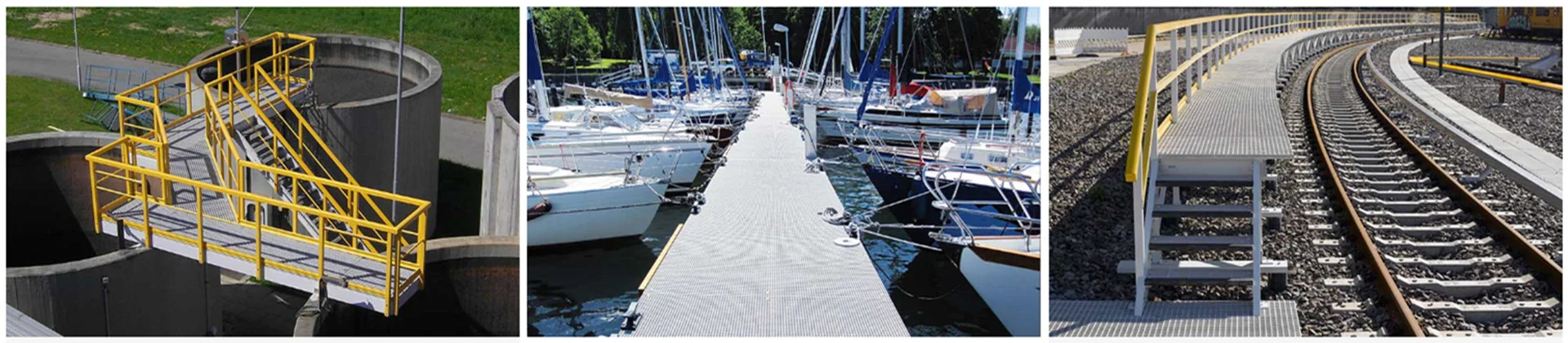
4. Application Examples: Where Pre-Drilled FRP Profiles Deliver the Most Value
4.1 FRP Fence and Railing Systems
Square tube fence rail systems use horizontal rails drilled to accept vertical post bolt connections. Pre-drilled rails arrive on site ready for bolt installation — no cutting equipment, no drilling equipment, no glass fiber dust in the installation area. In chemical plant railing replacement projects, Unicomposite’s project teams have consistently found that pre-drilled FRP profiles are specified specifically to avoid hot-work permit requirements in classified hazardous areas — a permit application that delays installation by 24–72 hours per work session on many petrochemical sites. Pre-drilled profiles remove the drilling step that triggers the permit requirement.
Handrail stanchion bases require precisely located bolt patterns matching foundation anchor bolt layouts established during concrete placement. CNC drilling holds the hole pattern to the structural drawing tolerance — field-drilled stanchion bases frequently require slotted holes or shimming to accommodate the position mismatch between drilled holes and actual anchor bolt positions.
4.2 Industrial Platform and Walkway Connections
FRP structural framing for elevated access platforms uses bolted beam-to-post and beam-to-beam connections where hole alignment across multiple members determines whether the frame squares up correctly. Pre-drilled members eliminate the alignment errors that accumulate when holes are drilled after partial erection.
In Unicomposite’s supply experience with industrial platform projects, the installation step that most consistently causes schedule delay is on-site drilling of connection holes in structural members after they have been lifted into position — a constraint that pre-drilled profiles remove from the installation critical path. Field modifications required by specification errors or as-built condition deviations may still require some on-site drilling, which is why complete specification at the order stage (Section 5) is the correct risk mitigation.
4.3 Power Utility Infrastructure
FRP cross arms for distribution line poles require precision-located insulator mounting holes whose position accuracy directly determines electrical clearance from the pole structure. CNC drilling holds the hole position to the tolerance required by utility installation drawings — a specification that hand drilling from field-transferred measurements cannot reliably meet across a production volume of hundreds or thousands of cross arms.
The table below maps application type to the primary benefit of pre-drilled profiles and the governing hole specification parameter:
| Application | Primary Benefit | Hole Specification Driver | Typical Profile Type |
|---|---|---|---|
| FRP fence / railing | No site power tools; no dust; no hot-work permits | Bolt pattern match to post layout | Square tube, flat bar |
| Industrial platform framing | Alignment accuracy across members | Hole position tolerance ±0.5 mm | I-beam, channel, angle |
| Power utility cross arms | Electrical clearance compliance | Hole position per utility drawing | Rectangular tube, flat bar |
| Cable management systems | Fast clip-and-channel assembly | Slot length and position accuracy | Channel, angle |
| Handrail stanchion bases | Anchor bolt layout match | Bolt circle diameter and pattern | Square tube, flat plate |
5. How to Specify Pre-Drilled FRP Profiles
The application examples above share a common specification requirement: every pre-drilled profile order that installs correctly without field modification begins with a complete and unambiguous specification document. The four elements below define what “complete” means for a pre-drilled FRP profile order.
5.1 Required Information for a Pre-Drilled Profile Order
Profile specification: cross-section type and size (per standard profile designation or dimensioned drawing), wall thickness, resin system (polyester, vinyl ester, or epoxy), and profile length.
Hole specification: hole diameter in millimeters, quantity per profile, and position coordinates — distance from the profile end face and from the profile centerline or datum edge, provided as a dimensioned drawing or coordinate table. Verbal descriptions (“centered at 150 mm from the end”) are insufficient for asymmetric cross-sections and should not be used as the sole position reference.
Edge sealing requirement: specify whether hole edges require resin sealing prior to shipment. For any chemical, marine, outdoor, or wet service environment, this is the correct default — the resin system must be identified so the correct compatible sealant grade is applied.
Order quantity: total number of profiles in the order, which determines whether CNC programming cost is amortized across a full production run or applied to a prototype sample quantity.
5.2 Common Specification Errors to Avoid
Three errors account for the majority of pre-drilled profile orders that require rework or reorder. First, specifying hole diameter without hole-to-edge minimum distance — holes positioned too close to the profile edge create insufficient bearing area; minimum hole-to-edge distance of 1.5× hole diameter is the standard minimum, and 2× hole diameter for high-load connections. Second, providing verbal position descriptions instead of dimensioned drawings — always provide a sketch with coordinates referenced to a fixed corner or end datum, not relative to a centerline that shifts with cross-section geometry. Third, omitting the resin system when edge sealing is required — the sealant must be chemically compatible with the profile matrix, and specifying edge sealing without identifying the resin system leaves the manufacturer unable to select the correct sealant grade.
Conclusion
Pre-drilled FRP profiles are not a premium upgrade — they are the correct procurement decision for any project where hole position accuracy, installation speed, site safety, and long-term corrosion protection all matter simultaneously. Four takeaways:
- FRP profile drilling requires carbide or diamond tooling, controlled feed rate, and back-plate support. Field drilling without these controls produces hole-edge delamination — up to 40% bearing area reduction — without any visible surface indication. The failure appears under load, not at inspection.
- Factory CNC drilling delivers ±0.5 mm positional accuracy, burr-free holes, integrated dust extraction, and full batch consistency. These are not marginal improvements over field drilling — they are capabilities that on-site hand drilling structurally cannot replicate.
- Pre-drilled profiles arrive job-site-ready. No power tools, no glass fiber dust, no PPE burden for hole-making, no hot-work permits in hazardous atmospheres. The installation crew installs fasteners.
- Provide a dimensioned hole position drawing, not a verbal description. Coordinate accuracy at the specification stage determines whether pre-drilled profiles install correctly without field rework — the most expensive outcome in a pre-drilled profile order is a hole pattern that does not match the connection hardware.
Frequently Asked Questions
The minimum wall thickness depends on the hole diameter and the structural requirement at the connection. As a general guideline, the wall thickness at the hole location should be at least equal to the hole diameter to maintain adequate bearing area around the fastener. For holes smaller than the wall thickness, standard drilling is straightforward; for holes approaching or exceeding the wall thickness, the connection design should be reviewed for bearing and pull-through capacity before specifying. Provide the wall thickness and hole diameter in your inquiry and Unicomposite’s engineering team will confirm feasibility.
Edge sealing at drilled hole perimeters is available as a factory finishing step and should be specified at the time of order. The resin sealant must be compatible with the profile’s resin matrix — polyester sealant for polyester profiles, vinyl ester sealant for vinyl ester profiles — so the resin system must be identified in the order specification. For any outdoor, marine, or chemical service environment, specifying edge sealing as part of the factory order is the correct default; omitting it and relying on field application is the most common cause of premature corrosion at drilled hole boundaries.
Yes — provide the bolt pattern as a dimensioned drawing with hole center coordinates referenced to a fixed datum point on the profile (typically the end face and one edge). If you have the metal member drawing, that document is the most reliable source for the bolt pattern — transfer the hole coordinates directly rather than re-measuring from the physical metal part, which introduces the same measurement transfer error that field drilling creates. Unicomposite can review the drawing and confirm hole position feasibility against the profile cross-section geometry before production begins.
Standard profiles in common resin systems with standard hole patterns typically require 2–4 weeks from confirmed drawing approval to shipment; contact Unicomposite at the inquiry stage for a specific production schedule confirmation before committing to an installation date. For projects with fixed installation windows, place the order with drawing approval at least 6 weeks before the required on-site date to allow for production, quality inspection, and shipping. Prototype samples for connection fit-check can typically be produced faster than full production runs — request samples as part of the initial inquiry if the connection detail has not been previously verified.
Yes — CNC drilling is compatible with FRP profiles in polyester, vinyl ester, and epoxy resin systems. The drilling parameters (RPM and feed rate) are adjusted for each resin system’s thermal properties and matrix hardness; epoxy profiles generally require slightly lower feed rates than polyester profiles to prevent heat buildup at the hole perimeter. The edge sealing material must match the profile’s resin system — specify the resin system in your order so the correct sealant grade is applied at the factory finishing step.


