 info@unicomposite.com


What Is an FRP Cable Tray and When to Use It
FRP cable trays are structural support systems made from fiber reinforced polymer profiles and fittings. Compared with traditional galvanized steel trays, FRP cable trays are lighter in weight, corrosion resistant, non-magnetic and electrically insulating, which makes them ideal for chemical plants, wastewater treatment facilities, coastal installations and other harsh or high-humidity environments.
Unicomposite supplies complete FRP cable tray systems including straight trays, covers, bends, tees, reducers, supports and hangers. For general information about tray types and applications, you can also refer to our fiberglass cable protection system section.
This guide focuses on the practical technical parameters for FRP cable tray installation, including tray specifications, support spacing and outdoor protection. It is written for engineers, contractors and maintenance teams who need to design or review FRP cable tray installation on industrial and commercial projects.

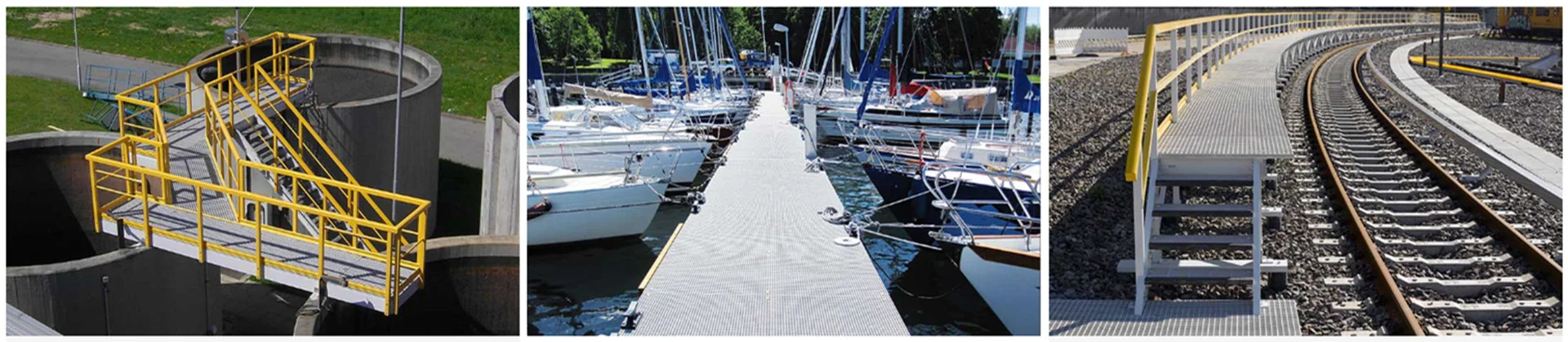
frp cable tray installation
FRP Cable Tray Specifications: Width, Height & Fill Ratio
Choosing the right FRP cable tray specification starts from the cables themselves. The width, height and allowable fill ratio will determine whether the cable tray system can safely carry the current load, allow heat dissipation and leave enough space for future expansion.
As a general engineering practice, the cable tray fill ratio should not exceed recommended values. Typical design targets are shown below; always compare with local electrical codes and project specifications.
| Cable type | Typical tray fill ratio | Design notes |
|---|---|---|
| Power cables | 40% – 50% of tray cross-section | Leave room for heat dissipation and easy maintenance. |
| Control and instrumentation cables | 50% – 70% of tray cross-section | Smaller cable diameters allow a slightly higher fill ratio. |
| Future expansion allowance | 10% – 25% spare capacity | Reserve space for additional circuits and modifications. |
When you determine tray width and height, sum the total cable area in each section and divide it by the allowed fill ratio. For example, if the cable bundle requires 6000 mm² of area and the design fill ratio is 50%, the minimum tray internal area should be 12000 mm². You can then select a standard FRP cable tray size that meets or exceeds this requirement.
For composite epoxy resin or pultruded FRP cable trays, the tray height is often increased for heavy power circuits or long spans to improve stiffness. Bends, tees and other fittings must match the selected tray width and height so that the mechanical strength and electrical performance of the entire system remain consistent.
FRP Cable Tray Supports & Hangers: Spacing and Selection
Proper design of supports and hangers is critical to ensure FRP cable tray installation meets load and deflection requirements. The spacing depends on tray size, load, environment and whether the installation is indoors or outdoors.
| Location | Typical support span | Remarks |
|---|---|---|
| Indoor straight runs | 1.5 m – 3 m between supports | Common spacing for standard loads in plant rooms and cable galleries. |
| Outdoor columns or building steel | Up to 6 m between vertical posts | Check wind, snow and ice loads; use heavier-duty FRP profiles if needed. |
| Non-linear sections (bends, tees, reducers) | Support close to each fitting | Add a support within 300 mm – 600 mm from each end of the fitting. |
| Large spans | >3 m | Use reinforced FRP beams, composite bridges or consult our engineering team. |
When the tray width is less than 300 mm, at least one support or hanger should be placed near the straight-to-bend transition. For tray widths above 300 mm, it is best practice to add an additional support at the middle of non-linear segments to limit deflection and torsion.
The support and hanger profiles should be made from compatible FRP materials or other corrosion-resistant materials so that the entire system offers consistent durability. For aggressive chemical environments, composite epoxy resin supports are recommended together with FRP trays to maximize service life.
Step-by-Step FRP Cable Tray Installation
Once the specifications and support spacing are defined, installation of FRP cable trays can follow a clear step-by-step sequence.
1. Site survey and layout planning
Walk through the route, confirm cable entry and exit points, identify obstacles, verify wall and steel structures for fixing, and mark anchor positions. At this stage it is helpful to coordinate with other trades to avoid clashes with HVAC ducts, piping or access walkways.
2. Install supports and hangers
Fix wall brackets, vertical columns or ceiling hangers according to the designed spans. Make sure all supports are level and aligned in both horizontal and vertical directions. For outdoor installations, check anchor bolts, chemical anchors or embedded plates for pull-out resistance and corrosion protection.
3. Install straight trays and fittings
Place FRP cable tray sections on the supports and join them with splice plates, bolts and washers recommended by the manufacturer. Tighten fasteners evenly and avoid over-torquing, which may damage FRP profiles. Install bends, tees and reducers and verify that all fittings are properly supported as specified earlier.
4. Provide expansion gaps and bonding
On long straight runs, leave an expansion gap of approximately 20 mm – 30 mm for metal tray connections every 50 m or as per project requirements. FRP trays do not rust, but when installed together with metallic systems or near high-voltage equipment, follow local electrical codes regarding bonding and grounding of supports or hardware.
5. Lay and secure cables
After the tray system has passed inspection, cables can be pulled or laid manually. Arrange cables by voltage and function, separate power and control circuits where necessary and do not exceed the specified fill ratio. Use non-metallic cable ties or clamps compatible with FRP, and avoid sharp edges that could damage cable sheaths.
6. Final inspection and documentation
Perform a visual inspection of all supports, splice joints, fittings and covers. Confirm that no tray section is overloaded, that walkways and access doors remain unobstructed and that identification labels are in place. Record tray sizes, spans and loading assumptions as part of the as-built documentation for future maintenance.
Outdoor Installation & Corrosion Protection for FRP Cable Trays
One of the key advantages of FRP cable trays is their excellent resistance to corrosion from moisture, salt spray and many chemicals. For strong corrosive environments or areas with flammable dust and liquids, we recommend composite epoxy resin FRP trays and covers for additional protection.
In outdoor applications, covers help protect cables from UV radiation, falling objects and accumulation of soot or dust. When trays cross public passages or roads, use bottom plates or solid-bottom tray sections in the crossing area to provide extra mechanical protection.
For coastal and chemical plants, it is also good practice to specify UV-stabilized resin systems and to inspect trays periodically for discoloration or surface chalking. When combined with properly selected supports and stainless steel fasteners, FRP cable tray systems can offer a very long service life with minimal maintenance.
Common Mistakes and Installation Tips
Several recurring issues can reduce the performance of an FRP cable tray installation. Paying attention to these points during design and construction will help avoid costly rework.
- Support spacing set too wide, resulting in excessive tray deflection or vibration under load.
- Tray fill ratio ignored, causing overcrowded cables, overheating risks and difficult maintenance.
- Using mismatched materials, such as carbon steel supports in corrosive environments together with FRP trays, which shortens overall system life.
- Insufficient expansion gaps or allowances at building expansion joints, which can stress the tray during temperature changes.
- Missing covers in dusty or outdoor areas, leading to contamination of cable jackets and additional cleaning work.
When in doubt about span, loading or environmental conditions, contact our technical team with your cable list, layout drawing and site photos. We can recommend appropriate FRP cable tray specifications, support spacing and accessories based on real project data.
FRP Cable Tray Installation FAQ
What is the typical support span for FRP cable trays?
For standard industrial loads, indoor FRP cable tray installations usually use support spans between 1.5 m and 3 m. Outdoor columns or building steelwork can be spaced up to around 6 m apart, provided the tray and support profiles are designed for the expected wind and snow loads.
How do I choose the right FRP cable tray width and height?
Start from the cable schedule, calculate the total cable cross-sectional area and then apply a suitable fill ratio. Power cables often use 40% – 50% of the tray cross-section, while control cables can reach 50% – 70%. Add 10% – 25% spare capacity for future expansion and select a standard tray size that meets or exceeds the calculated requirement.
Can FRP cable trays be used outdoors in coastal or chemical environments?
Yes, FRP cable trays are particularly suitable for harsh outdoor conditions. For strong corrosive environments and coastal sites, we recommend composite epoxy resin trays, corrosion-resistant supports and covers to protect cables against UV, chemicals and falling debris.
Where can I get engineering support for my FRP cable tray installation?
If you are planning a new project or upgrading an existing cable support system, you can send your requirements to our team via the contact form. We can help you review tray specifications, support spans and installation details to ensure a safe and efficient FRP cable tray installation.


