 info@unicomposite.com


Introduction
A cable run rarely fails because the tray is “too weak.” It fails because the supporting hardware ages badly—corrosion at bolt lines, loosened joints, or brackets that were never sized for real-world loads and exposure.
This guide helps B2B buyers and engineers specify FRP Cable Support Brackets with fewer surprises: what they are, where they make sense, how to choose materials and hardware, how to install them correctly, and what to verify at receiving and commissioning.
Unicomposite is an ISO-certified pultrusion manufacturer producing standard FRP profiles and custom composite parts for sectors like power utilities, wastewater, marine, cooling towers, agriculture, and OEM fabrication. That matters here because bracket performance is often about consistency (batch-to-batch) and fit-up (custom interfaces) more than glossy specs.
“Most bracket issues aren’t sudden failures—they’re slow, predictable corrosion and loose connections nobody planned for.” — Field maintenance lead

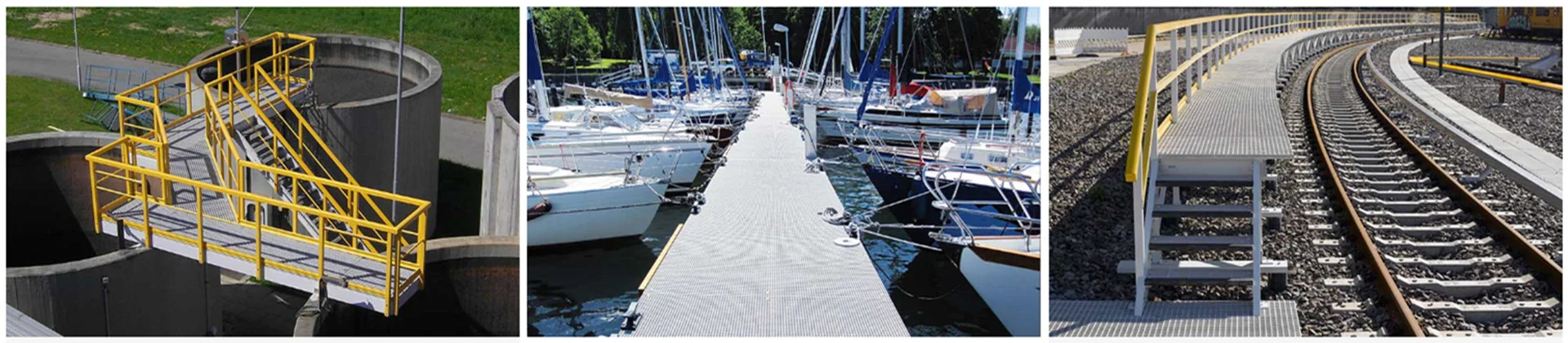
frp cable support brackets
What FRP Cable Support Brackets Are
FRP cable support brackets are structural supports—cantilever arms, multi-tier frames, base plates, and connection hardware—used to carry cable trays, ladder racks, conduits, and bundled cables along walls, columns, trenches, and pipe racks.
Common configurations (you’ll see these on most BOMs):
- Wall-mount cantilever arms (single-tier or multi-tier)
- Column-mount bracket systems (straps/clamp plates + arms)
- Stanchions + arms for cable corridors and trench routes
- Braced arms for higher loads and longer projections
A major reason projects switch from metal to FRP is that the “material advantage” shows up in handling and corrosion exposure. As a reference point, steel density is about 7.85 g/cm³, while many fiberglass composites are roughly 1.8–2.0 g/cm³—often near ¼ the weight for comparable geometry. (Verify exact values on your product datasheet.)
“When crews can carry and position brackets without fighting the weight, install quality improves.” — Installation foreman
Where FRP Brackets Win (and Why)
Power utilities, substations, and cable trenches
FRP is frequently chosen where dielectric behavior and moisture coexist:
- non-conductive by design (system-level safety benefit)
- less dependence on coatings in wet trenches or washdown areas
- reduced galvanic/stray-current corrosion risk at interfaces
Practical planning metric: many owners reserve 20–30% capacity for future cable additions on critical routes, then size bracket spacing and section selection accordingly.
“If your site has standing water two months a year, you’re basically running a corrosion lab.” — EPC site supervisor
Wastewater, chemical-adjacent zones, and corrosive industrial sites
This is where maintenance budgets get eaten alive. The hidden cost of metal supports is not just rust—it’s the recurring cycle of inspection, recoating, and replacement at cut edges and bolt interfaces.
First-hand project note: On a coastal corridor retrofit I helped review, the metal brackets didn’t fail in the middle of the arm—failure started at the bolt line: coating damage, corrosion creep, then joint looseness. The fix wasn’t “stronger metal.” We revised the detail: larger backing plates, better hole edge distance, consistent washer/plate sizing, and an environment-appropriate fastener spec. The punchline: fewer re-torques and fewer emergency work orders in the next inspection cycle.
“The cheapest bracket is the one you don’t have to touch for years.” — Municipal maintenance planner
Marine, coastal, cooling towers, and high-humidity structures
Salt fog and temperature swings punish coatings fast—especially at drilled holes and scratched surfaces. FRP reduces coating dependence and typically speeds small retrofit installs thanks to lower component weight.
“Coastal air finds every scratch. Brackets fail at the bolt line long before the main structure does.” — Marine facility technician
How to Specify: Selection Rules Buyers Can Execute
1) Start with load, spacing, and bolt-line stress
Build a simple load model before shopping catalogs:
- tray/ladder self-weight
- installed cable weight (plus growth allowance)
- localized point loads (drops, transitions)
- vibration/wind if relevant
Mini example (simplified):
If a tray segment plus cables is 30 kg per meter, and brackets are spaced every 1.5 m, the gravity load “seen” per bracket is roughly 45 kg (before safety factors and dynamic allowances). That number then informs:
- arm section choice (deflection control)
- connection plate sizing (reduce crushing around holes)
- fastener/washer strategy (joint reliability)
“Most spec misses come from underestimating the joint—bolt-line stress, not arm strength.” — Structural detailer
2) Match environment → resin/surface → fasteners (decision guide)
Use this as a practical starting point, then confirm with your supplier’s datasheet and project requirements:
- Mild indoor / low corrosion
- Resin/surface: general industrial-grade FRP may be sufficient
- Fasteners: corrosion-protected metals often acceptable (site-dependent)
- Moderate corrosion / frequent moisture
- Resin/surface: higher chemical-resistance systems are commonly preferred
- Fasteners: upgrade to corrosion-resistant options; prioritize joint protection
- Severe corrosion / splash zones / coastal salt exposure
- Resin/surface: specify high resistance + surface veil/coating strategy for durability
- Fasteners: treat fasteners as “critical”—select accordingly and standardize washers/plates
- Outdoor UV exposure (any level)
- Add UV strategy: surface veil, coating, and storage/handling rules to prevent premature aging
“The environment decides the resin; the drawings don’t.” — Composites application engineer
3) Use a parameter sheet to prevent change orders
Copy/paste this into your RFQ—buyers and engineers can fill it together.
FRP Cable Support Brackets — Parameter Sheet (Template)
| Item | Your Requirement | Notes |
|---|---|---|
| Site environment | Mild / Moderate / Severe | Include chemicals, salt fog, splash exposure |
| Location | Indoor / Outdoor | UV exposure? temperature swings? |
| Bracket type | Wall / Column / Stanchion / Multi-tier | Provide route photos if retrofit |
| Arm projection | ___ mm | Clearance constraints matter |
| Bracket spacing | ___ mm | Based on load + deflection limits |
| Estimated load | ___ kg per meter | Include growth allowance |
| Tray/ladder interface | Brand/model or drawing | Hole pattern alignment reduces rework |
| Substrate | Concrete / Steel / FRP structure | Anchor details required |
| Fastener preference | ___ | Include washers/plates requirement |
| Fire requirements | Yes/No + documentation | Enclosed corridors often stricter |
| Documentation | Drawings, traceability, inspections | Define “must-have” items |
| Packaging | Edge protection, labeling | Prevent shipping damage |
Unicomposite’s manufacturing setup (pultrusion + custom fabrication and other composite forming options) is useful when your interface detail isn’t standard—custom base plates, gussets, clamp plates, and mixed-material connections are where projects typically lose time.
“Customization saves money when it prevents field drilling, shimming, and rework.” — Project manager
Installation, Safety, and Handling
Installation SOP (field-friendly)
- verify layout (elevations, spacing, substrate strength)
- pre-check kits (hole patterns, hardware completeness)
- install bases/anchors → mount arms → confirm level/plumb
- torque control + anti-loosening approach
- record and inspect (photos, measurements, batch IDs)
Key numbers that help execution:
- do a first-article assembly check on 1 kit before full rollout
- spot-check torque and joint fit-up at every route transition (highest risk points)
“Over-torque is the silent killer—FRP doesn’t complain until it’s already damaged.” — QA inspector
Safety & handling considerations
- cutting/drilling: use dust control and appropriate PPE; seal cut edges if required by your durability spec
- hole finishing: avoid splintering; use correct drill bits and backing support
- joint protection: standardize washers/plates to prevent localized crushing
- storage: keep out of prolonged direct sunlight before install if UV strategy is critical
Quality, Receiving, and Acceptance Checklist
Documentation acceptance (before parts hit site)
Require a clean pack:
- drawings or dimensional specs (including hole patterns)
- resin/surface identification as applicable
- batch traceability and inspection records
- any fire-performance or project-specific documentation requirements
ISO-certified processes and traceability practices are particularly valuable on bulk orders where consistency is a performance feature.
“In bulk buys, consistency is a performance feature.” — Procurement quality manager
Receiving inspection (at delivery)
Use a simple sampling rule: 5% of pieces or 5 units minimum, whichever is greater.
- verify dimensions and hole spacing against drawings
- confirm kit completeness (hardware, plates, labels)
- inspect edges and surfaces (no severe fiber exposure, shipping damage, or deformation)
- dry-fit one assembly to your tray/ladder interface before accepting full rollout
Installation acceptance (during commissioning)
- verify spacing matches plan (don’t “field-stretch” spacing)
- confirm joint hardware is consistent across the route
- document any field cuts and confirm edge sealing procedure is followed
- record final photos at transitions, supports, and high-load areas
“The best suppliers don’t just ship parts—they prevent the next change order.” — EPC buyer
Cost Logic: When FRP Is Worth It (and When It Isn’t)
A practical lifecycle cost view:
- purchase price + install labor
- maintenance and inspection frequency
- downtime risk in corrosive/poor-access zones
- replacement cycles driven by exposure and hardware selection
FRP may be unnecessary where conditions are mild, access is easy, and the project duration is short. A pragmatic strategy is zone-based specification: deploy FRP where corrosion and access make maintenance expensive; keep simpler systems where conditions are forgiving.
“If access is difficult, maintenance costs more than materials—every time.” — Plant operations supervisor
Conclusion
A reliable FRP bracket system is less about the word “FRP” and more about five decisions: load/spacing, environment/resin/UV strategy, fire/electrical requirements, joint hardware, and installation discipline.
If you’re building a BOM, start by filling the parameter sheet, validate a sample kit against your tray interface, then lock the fastener/plate standard and installation SOP. For non-standard geometries or high-exposure sites, working with an ISO-controlled manufacturer like Unicomposite—capable of consistent pultrusion output plus custom composite fabrication—can shorten design loops and reduce field rework.
Frequently Asked Questions
Yes, when sized correctly. The bracket arm is only part of the story—spacing, projection, and joint hardware (plates/washers/fasteners) often govern real-world performance.
In corrosive environments, fasteners can become the weak link. Treat the joint as a system: select fasteners appropriate for exposure and standardize plates/washers to reduce crushing and loosening.
Define the UV strategy and storage/handling expectations, not just “outdoor rated.” Ask about surface veil/coating options and ensure cut-edge handling matches the durability requirement.
Choose custom when clearance constraints, multi-tier routing, unusual substrates, or non-standard interfaces would otherwise force field drilling and rework. Customization can reduce labor and improve consistency.
Verify dimensions and hole patterns against drawings, confirm kit completeness, inspect edges/surfaces, and dry-fit at least one assembly to your tray/ladder interface before approving full rollout.


