 info@unicomposite.com


Introduction
When a robotic arm undershoots its payload rating or a UAV fails flight certification because the frame weighs 200 grams too much, the problem rarely traces back to a design flaw. More often, it traces back to a material selection decision made early in the procurement process. Engineers who moved from aluminum to carbon fiber reinforced polymer (CFRP) tubes typically do not go back — not because CFRP is fashionable, but because the performance data makes the case on its own.
This guide covers the principal industrial carbon fiber tube applications, how CFRP performs against aluminum and steel across the eight metrics that drive OEM structural decisions, and what procurement teams should verify before committing to a production order.

carbon fiber tubes
What Makes Carbon Fiber Tubes the Engineering Default for Demanding Applications?
The short answer: no other commercially available structural tube delivers comparable stiffness at comparable weight. The longer answer involves understanding why that matters differently across applications — and where CFRP’s advantages are decisive versus merely incremental.
Mechanical Properties: Specific Stiffness, Tensile Strength, and Fatigue Resistance
Standard industrial CFRP tubes achieve tensile strengths in the range of 600–1,500 MPa depending on fiber grade, orientation, and resin system — significantly higher than 6061 aluminum at 270 MPa or structural steel at 400–550 MPa. More important than raw tensile strength for most structural tube applications is specific stiffness: the ratio of elastic modulus to density.
CFRP’s specific stiffness is roughly 3–5× higher than aluminum and 5–7× higher than steel. In practical terms, this means engineers can achieve the same deflection performance with a tube that weighs a fraction of the metallic equivalent — or achieve substantially better deflection performance at the same weight budget.
Fatigue behavior is a less-discussed but equally important advantage. Metallic tubes accumulate fatigue damage cyclically, with crack propagation accelerating over time under repeated loading. CFRP tubes fail through a fundamentally different mechanism — delamination and fiber breakage rather than crack propagation — which gives them predictable, gradual degradation behavior that engineers can design around. In vibration-critical assemblies such as high-speed spindles or oscillating measurement arms, procurement teams consistently report that CFRP components outlast aluminum equivalents by a factor of two or more in fatigue life.
Roll-Wrapped vs. Pultruded Carbon Fiber Tubes
The manufacturing method determines the tube’s structural behavior as much as the fiber grade does. Buyers who specify CFRP tubes without clarifying the construction method often receive a product optimized for the wrong load direction.
The table below compares the two dominant production methods for industrial CFRP tubes across the dimensions most relevant to OEM structural design:
| Characteristic | Roll-Wrapped | Pultruded |
|---|---|---|
| Fiber orientation | Custom — 0°, ±45°, 90°, or combined layups | Primarily 0° (axial) |
| Primary strength direction | Multi-axial — tunable for torsion or hoop loads | Axial — highest stiffness along tube length |
| Dimensional flexibility | High — custom OD, ID, and wall thickness per spec | Moderate — limited to die geometry |
| Surface finish | Raw carbon, matte or gloss clearcoat | Typically raw or lightly sanded |
| Typical applications | Robotic arms, drone frames, precision instruments | Structural beams, column supports, long-run profiles |
| Relative unit cost | Higher — labor-intensive layup | Lower — continuous, automated process |
Roll-wrapped tubes suit applications with complex load cases — torsion, bending in multiple planes, or combined loads. Pultruded tubes are the cost-effective choice when the primary load is axial and the cross-section is constant along the tube’s length.
Selecting the wrong construction type for a given load case is the most common specification error buyers make — and it typically only surfaces during prototype testing rather than at the order stage.
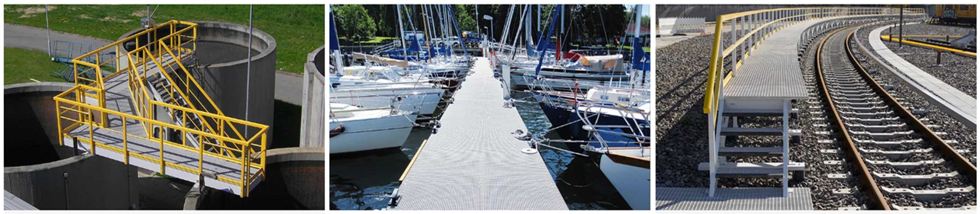
Primary Carbon Fiber Tube Applications in Industry
Beyond the material fundamentals, the real-world value of CFRP tubes becomes clear when mapped to specific application categories. Each use case places different demands on the tube’s geometry, surface quality, and mechanical profile.
Robotics and Industrial Automation Arms
In robotic arm design, every gram of structural weight reduces the effective payload capacity or forces an upsize of the drive motor — both costly outcomes. CFRP tubes allow engineers to maintain arm rigidity while reducing structural mass, shifting the weight budget toward end-effectors, sensors, or extended reach.
An anonymized example from the precision assembly sector illustrates the impact: a robotics OEM replaced aluminum structural tubes in a six-axis arm’s third and fourth links with roll-wrapped CFRP equivalents of the same outer diameter. Arm weight dropped by 31%, which allowed the existing servo motors to achieve 18% higher payload capacity without hardware replacement. The precision diameter tolerance required was ±0.05 mm — a specification that drove the choice of roll-wrapped over pultruded construction.
Key specifications for robotic arm CFRP tubes: tight OD/ID tolerances (±0.05–0.10 mm), high axial and torsional stiffness, and surface finish compatible with adhesive bonding at joint interfaces.
UAV Frames and Drone Structural Components
In unmanned aerial systems, frame weight directly determines flight time, payload capacity, and maneuverability. Regulatory payload categories are fixed — the only variable a manufacturer controls is structural mass. CFRP tubes have become the default material for UAV booms, landing gear struts, and frame crossmembers precisely because the weight advantage is non-negotiable at scale.
A further advantage in UAV applications is electromagnetic transparency. CFRP tubes do not interfere with GPS, RF communication, or compass signals — a critical property that metallic tubes cannot match without shielding workarounds. Typical wall thickness for UAV structural tubes ranges from 0.5 mm to 2.0 mm, with ±45° biaxial fiber orientation providing the torsional resistance needed in multi-rotor configurations.
Medical Imaging and Diagnostic Equipment
CT scanner gantries, X-ray positioning tables, and surgical robot arms impose a dual requirement that CFRP uniquely satisfies: high structural rigidity under dynamic loads and radiolucency — the property of not absorbing or scattering X-ray energy. Aluminum and steel are both radiopaque; their presence in the imaging field distorts results. CFRP is radiolucent by nature.
For patient-contact or body-adjacent components, procurement teams should confirm ISO 10993 biocompatibility testing with the supplier before finalizing the specification. Not all resin systems used in CFRP tube manufacturing meet biocompatibility standards, and this distinction matters in a regulatory environment.
Precision Instruments and Metrology Equipment
Coordinate measuring machine (CMM) probes, optical instrument frames, and large-format telescope tubes all share a requirement that goes beyond strength: dimensional stability under temperature variation. The coefficient of thermal expansion (CTE) of standard CFRP is approximately 0–2 ppm/°C, compared to 23 ppm/°C for aluminum. In a laboratory environment with ±5°C temperature variation, an aluminum tube 1,000 mm long will expand or contract by up to 115 μm — enough to invalidate micrometer-level measurements. A CFRP tube under the same conditions may shift by 10 μm or less.
Engineers specifying CFRP tubes for metrology applications should also account for CTE mismatch at bonded or fastened joints. Where a CFRP tube interfaces with an aluminum housing or steel fixture, differential thermal expansion creates stress at the bond line. Selecting a low-modulus adhesive or designing for slip in one axis can mitigate this without compromising the performance advantage.

performance of carbon fiber tubes
CFRP Tube vs. Aluminum vs. Steel: A Material Comparison
The choice of structural tube material should be driven by quantitative comparison, not convention. The table below covers the eight dimensions most relevant to OEM structural tube selection:
| Property | CFRP Tube | 6061 Aluminum | Carbon Steel |
|---|---|---|---|
| Density (g/cm³) | 1.5–1.6 | 2.7 | 7.85 |
| Tensile strength (MPa) | 600–1,500 | 270 | 400–550 |
| Specific stiffness (GPa·cm³/g) | 60–100+ | 26 | 27 |
| Corrosion resistance | Excellent — no coating required | Good — oxidizes, requires anodizing in harsh environments | Poor — galvanizes or paints required |
| CTE (ppm/°C) | 0–2 | 23 | 11 |
| Electrical conductivity | Non-conductive (standard epoxy resin) | Conductive | Conductive |
| Machinability | Requires diamond or carbide tooling; dust control needed | Excellent | Good |
| Relative material cost | High | Low | Very low |
Three observations stand out for procurement teams evaluating this comparison. First, CFRP’s specific stiffness advantage over aluminum is not marginal — it is structural-class-changing. Second, the CTE advantage in thermal environments is often the deciding factor in precision applications, independent of cost. Third, machinability requires investment in appropriate tooling and dust extraction; teams that overlook this underestimate on-site fabrication cost.
Specification Checklist for OEM Buyers
Knowing the application is only half the specification task. Translating application requirements into a procurement document that generates comparable quotes from multiple suppliers requires clarity on five dimensions.
Diameter, Wall Thickness, and Fiber Orientation
Standard industrial CFRP tubes are available in outer diameters from 6 mm to 200 mm, with wall thicknesses from 0.5 mm to 10 mm. For roll-wrapped tubes, buyers can specify fiber layup by winding angle: 0° provides maximum axial stiffness, ±45° maximizes torsional resistance, and 90° (hoop windings) increases resistance to external radial pressure. Most structural applications use a combined layup — for example, [0°/±45°] — that balances axial and torsional performance.
Procurement teams should specify both OD and ID tolerances explicitly. Loose tolerances (±0.2 mm) are appropriate for non-precision structural members; precision applications such as CMM arms or robotic joint interfaces typically require ±0.05 mm or tighter, which drives both supplier selection and unit cost.
Surface Finish, Tolerances, and Resin Systems
Surface finish options include raw carbon fabric, matte clearcoat, gloss clearcoat, and paint-primer over the laminate. Raw carbon is specified when the tube will be bonded or overwrapped; clearcoat is appropriate for visible components. For aggressive chemical environments — process piping shrouds, wastewater facility infrastructure — vinyl ester resin provides substantially better chemical resistance than standard epoxy. Buyers should confirm the resin system in writing as part of the purchase specification.
Before placing a bulk production order, procurement teams should request the following documentation from the supplier: fiber grade certificate, resin system datasheet, tensile and flexural test results per ASTM D2584 or equivalent, dimensional inspection report for the first article, and — for regulated applications — any applicable ISO or industry-specific certifications.
Why Leading OEMs Source CFRP Tubes from Specialized Manufacturers
The technical performance of a carbon fiber tube is inseparable from the consistency of the manufacturing process that produced it. Diameter variation of 0.15 mm across a production batch, a void fraction above 2% in the laminate, or inconsistent fiber orientation between production runs will degrade field performance even when the average properties appear acceptable.
Unicomposite Technology Co., Ltd., ISO 9001-certified and operating from an 18,000 m² manufacturing facility in Nanjing, produces both roll-wrapped and pultruded CFRP tubes for OEM and industrial clients across North America and Asia-Pacific. The company provides standard catalog sizes alongside fully engineered custom configurations — including non-standard fiber orientations, hybrid fiber constructions (carbon-glass), and application-specific resin systems — with engineering consultation available for complex load cases.
Engaging a manufacturer with documented process controls and the capacity to support engineering review at the specification stage is the most direct way to reduce qualification risk for first-production orders.
Conclusion
Carbon fiber tube applications span a wider range of industries than most procurement teams initially recognize — from robotics and UAVs to medical imaging and precision metrology. Across all of them, four principles apply:
- Match the construction method to the load case. Roll-wrapped for multi-axial and torsional loads; pultruded for cost-efficient axial stiffness.
- Specify fiber orientation explicitly. A tube labeled “carbon fiber” without a fiber layup specification is an incomplete procurement document.
- Request third-party test data, not just supplier datasheets. Tensile and flexural properties per ASTM D2584 or ISO 14129 provide a verifiable performance baseline.
- Account for CTE in thermally variable environments. The dimensional stability advantage of CFRP over aluminum is often the decisive factor in precision applications — and it is frequently overlooked at the specification stage.
[Contact Unicomposite for carbon fiber tube specifications and a custom OEM production quote →]
Frequently Asked Questions
Industrial CFRP tubes are commonly produced using standard modulus (T300-grade, ~230 GPa), intermediate modulus (~290 GPa), or high modulus fiber (~370 GPa+). Higher modulus fiber increases stiffness but reduces strain-to-failure — a trade-off that matters in impact-prone applications. For most OEM structural uses, standard modulus fiber offers the best balance of stiffness, toughness, and cost. Buyers should specify the fiber grade, not just “carbon fiber,” when requesting quotes.
Yes. Hybrid layups combining carbon fiber for stiffness with E-glass for impact toughness and cost reduction are available from manufacturers with multi-fiber winding capability. The typical configuration places carbon at 0° for axial stiffness and glass at ±45° for hoop and torsional load handling. Buyers should provide the application load case so the supplier can recommend an appropriate hybrid ratio.
At minimum, buyers should request ISO 9001 certification from the manufacturer, first-article inspection reports, and mechanical test results per ASTM D2584 (fiber volume fraction) or ASTM D790 (flexural properties). Medical and aerospace applications may require additional material traceability documentation. Confirm specific regulatory requirements with your quality team before finalizing the supplier specification.
Standard catalog sizes generally ship within 5–10 business days. Custom configurations — non-standard fiber orientation, precision tolerances, or non-catalog OD/ID combinations — typically require 15–30 production days after engineering review and first-article approval. Building qualification time into the project schedule before production launch reduces downstream risk.
CFRP can be machined, drilled, and cut with appropriate tooling — carbide or diamond-coated bits are required; standard high-speed steel tools wear rapidly and produce rough edges. Drilling generates fine respirable dust, so industrial dust extraction and respiratory protection are mandatory. For precision-tolerance machined ends or threaded inserts, most OEM buyers specify these as part of the tube order rather than machining in-house.


