 info@unicomposite.com


Introduction
Reviewed by the Unicomposite Engineering Team (ISO-certificated pultrusion manufacturer).
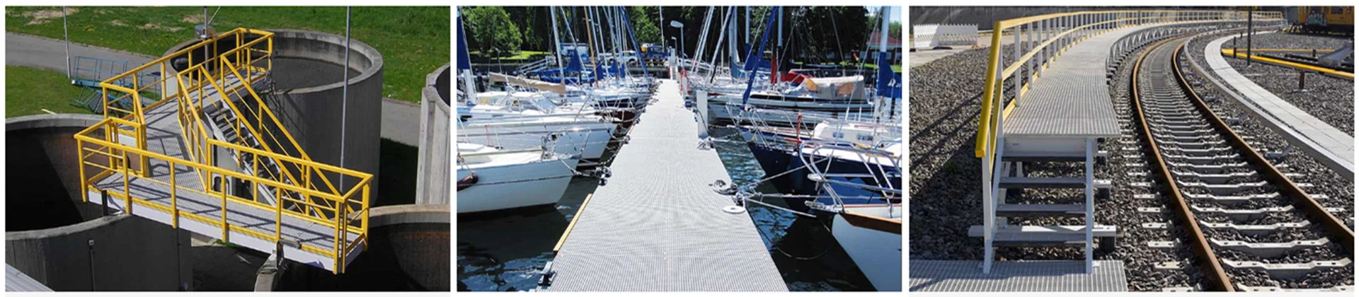
When designers compare options for platforms, walkways, scrubber decks, and utility frames, fiber-reinforced polymer (FRP) beams stand out for corrosion resistance, low weight, and dielectric safety. This practical guide shows how to pick sections, check strength and serviceability (including creep), and detail connections so your first composite project feels familiar—not experimental.
“Treat FRP like an engineered, orthotropic material—not ‘plastic steel.’ Put serviceability up front and your project will fly.” — Senior Project Engineer
Unicomposite supports engineers with standard I-beams, channels, and boxes—and custom layups when stiffness, creep, or environment demand it—plus QA documentation and shop-friendly detailing support.

design of frp beams
FRP Fundamentals for Beam Design
What a pultruded FRP beam is (I-beam, channel, box, custom)
Pultrusion draws continuous glass fibers through resin and a heated die, yielding constant-section profiles: I-beams for bending efficiency, channels for edges and secondary framing, and box sections where torsion or lateral stability governs.
Material properties & variability
FRP is orthotropic. Longitudinal properties (parallel to fibers) are high; transverse and shear are lower. Properties depend on layup, fiber volume fraction, and resin. Specify minimums and require lot-level QA so design values match supplied product.
Environment & durability inputs
Temperature, moisture, chemicals, and UV influence both strength and long-term deflection. Vinyl ester is common for aggressive media; surfacing veils and UV topcoats preserve color/finish and slow micro-cracking.
Codes, Standards & Design Philosophy
Which documents to use and why
Align with recognized FRP design guides and your Authority Having Jurisdiction (AHJ). Confirm whether the project uses LRFD or ASD language and how environmental/duration reduction factors are applied.
Limit states and resistance format
Design for ultimate limit states (flexure, shear, bearing) and serviceability (deflection, vibration, creep). Document knock-downs and assumptions in your calc package.
Load combinations & use categories
Industrial platforms often combine uniform live load, concentrated maintenance loads, wind, and thermal effects. Note walk-induced vibration where people congregate.
Step-by-Step Beam Sizing Workflow
Define span, boundary conditions, and loads
Confirm clear span and support stiffness. For walkways include grating self-weight, MEP, and occasional point loads. Do a quick hand calc to sanity-check your software output.
Select a section & orientation
I-beams are efficient for bending; box sections shine where torsion or lateral-torsional buckling (LTB) threatens. Favor depth for stiffness before chasing flange thickness.
Strength checks
-
Flexure: Compression flange stability, local buckling, section capacity with environment/duration reductions.
-
Shear: Web shear and web-flange junction.
-
Bearing/crippling: At supports and point loads; use bearing plates or shear clips as needed.
Serviceability checks
-
Immediate deflection: Start with L/300 for pedestrian comfort unless the spec says otherwise.
-
Creep: Estimate long-term (sustained) deflection with a project-appropriate multiplier.
-
Vibration: Keep natural frequencies comfortably above pacing rates for narrow walkways.
Torsion & lateral stability
Provide lateral bracing or choose closed sections where torsion enters. If grating clips/handrails offer restraint, document the assumed stiffness.
Reference Design Example (7 m walkway beam)
Assumptions (illustrative—verify with supplied certs and project specs):
-
Simply supported span L = 7,000 mm; service uniform load w = 2.5 N/mm (≈2.5 kN/m) including self-weight.
-
Candidate pultruded I-beam (depth ≈ 250 mm).
-
E₁ = 26,000 N/mm²; candidate moments of inertia I shown below.
-
Immediate deflection formula: δ = 5wL⁴ / (384EI). Limit: L/300 = 23.3 mm.
-
Creep multiplier for sustained load (starting point): 1.5×.
Immediate midspan deflection
-
I = 6.5×10⁷ mm⁴ → δ ≈ 46.2 mm (fails)
-
I = 1.3×10⁸ mm⁴ → δ ≈ 23.1 mm (meets immediate)
-
I = 2.5×10⁸ mm⁴ → δ ≈ 12.0 mm (comfortable)
Creep check (long-term ≈ 1.5× immediate)
-
I = 1.3×10⁸ → ~34.7 mm (exceeds L/300)
-
I = 2.5×10⁸ → ~18.0 mm (passes)
Strength sanity check
M_max = wL²/8 ≈ 15.3 kN·m. With beam depth ≈ 250 mm → c ≈ 125 mm; Z = I/c. For I = 2.5×10⁸ mm⁴: Z ≈ 2.0×10⁶ mm³ → bending stress σ ≈ 7.7 MPa (well below typical reduced allowables), so serviceability governs.
Shear: V_max = wL/2 ≈ 8.75 kN. With web ≈ 10 mm × 230 mm, average τ ≈ 3.8 MPa—usually acceptable relative to reduced shear allowables.
Takeaway: Select the deeper section (≈2.5×10⁸ mm⁴) or switch to a closed box to control long-term deflection.
Quick-Reference Tables (starting values—confirm with supplier data)
Table 1: Typical pultruded property ranges (room temp, dry)
| Property (parallel to fibers) | Typical Range |
|---|---|
| Elastic modulus E₁ | 20–35 GPa |
| Shear modulus G₁₂ | 3–5 GPa |
| Tensile strength (parallel) | 200–400 MPa |
| Compressive strength (parallel) | 150–250 MPa |
| Interlaminar shear strength | 20–40 MPa |
| Density | 1,700–2,000 kg/m³ |
Table 2: Starting environmental/duration reductions
(Apply multiplicatively; choose project-appropriate factors and verify with certs.)
| Effect | Starting factor |
|---|---|
| Wet service / chemical splash | 0.75–0.85 |
| Elevated temperature (near resin Tg) | 0.70–0.85 |
| Sustained load (creep envelope) | 0.65–0.85 |
| UV exposed (with topcoat) | 0.90–0.95 |
Table 3: Drilling & edge distance (typical minima)
| Item | Starting value |
|---|---|
| Edge distance (from hole center) | ≥ 2.0 × hole diameter |
| End distance (from cut end) | ≥ 2.5 × hole diameter |
| Hole tolerance | +0.2/−0.0 mm; clean, supported cut |
| Deburring | Light chamfer to reduce stress risers |
Connections, Details & Fabrication
-
Bolted joints: Use carbide tooling; stainless hardware with insulating washers when touching metals; respect edge distances; publish torque values.
-
Adhesive & hybrid joints: Improve load sharing and sealing; ensure surface prep and peel control; hybrid bolt-bond provides redundancy.
-
Supports & interfaces: Seat on FRP/neoprene pads; allow differential movement against steel/concrete; seal end cuts in splash zones.
-
Fire/UV: For enclosed areas, specify resin/coatings to meet FST criteria; add UV-stable veils/topcoats outdoors.
Durability, Inspection & Life-Cycle Cost
-
Creep & fatigue: Limit sustained stress ratios; check fatigue for repetitive traffic.
-
Corrosion & dielectric advantages: No rust; electrical insulation near substations/rail traction.
-
Inspection: Annual visuals, torque audits, coating touch-ups; track lot numbers; keep a simple log.
-
Life-cycle: Fewer shutdowns, lighter lifts, and minimal corrosion work often beat steel on multi-year TCO.
Case Study (Anonymized)
Brief: Wastewater plant replaced corroded steel beams on a 1.2-m walkway; spans 6–8 m; splash-zone; non-conductive requirement.
Design: Pultruded I-beams (vinyl ester + UV topcoat), deflection limited to L/300 under D+L; bolted seat clips standardized.
Outcomes: Weekend change-out cut crane time by ~35%, midspan deflection measured within 3–5 mm of prediction, and the maintenance team formalized torque checks in the CMMS.
Safety Considerations
Cutting/drilling FRP generates fine dust—use extraction, P2/P100 respirators, eye/skin protection, and control ignition sources near resin. Seal cut edges in corrosive service. Follow manufacturer SDS and site hot-work rules.
Procurement & Specification Toolkit
7.1 Pre-bid checklist
Data sheets (minimum properties), QA plan, lot traceability, sample coupons (tension, shear), Barcol hardness, installation method statements, torque procedures.
7.2 Spec language starter (drop-in snippet)
7.3 Submittals & QC testing
Request mill certs by lot, random coupon testing, acceptance criteria for holes/cut edges/finish, and on-site hold points.
Expert Insights & Pro Tips
-
Depth beats thickness: Choose a slightly deeper section before upsizing flanges—it slashes creep deflection.
-
Mind the holes: Back up laminates while drilling; chamfer to cut stress risers.
-
Model assumptions: If grating/rails brace the compression flange, state the stiffness in calcs and drawings.
Standards & References consulted (short list)
ASCE/LRFD prestandard for pultruded FRP structures; EN 13706 (profiles); ASTM D3039/D695/D790/D2344/D7290 (mechanical/design values). Confirm project-specific requirements with the AHJ.
How Unicomposite Supports Your Project
As an ISO-certificated pultrusion manufacturer, Unicomposite supplies standard and custom profiles and partners with design teams to tune layups for stiffness, creep control, and environment. We help with section selection, connection detailing, and QA/QC documentation across power, marine, wastewater, and OEM applications—keeping your submittals and shop drawings moving. A short concept-stage review often removes a full redesign cycle.
Conclusion
FRP beams excel where corrosion resistance, low weight, and dielectric safety matter. Use a serviceability-first workflow, pick depth for stiffness, control creep with honest reductions, and detail joints for repeatable field work. With aligned specs and a manufacturing partner, composite beam design becomes straightforward—and reliable—for industrial platforms, treatment plants, and coastal structures.
Call to action: Share your span, loads, and environment; Unicomposite will propose candidate sections, reductions, and detailing notes for a clean first pass.
Frequently Asked Questions
Q1: How do I control long-term (creep) deflection?
Select deeper or closed sections, apply realistic duration factors, and where possible reduce sustained loads. Validate with supplier design values and consider periodic bracing.
Q2: When should I choose a box section instead of an I-beam?
Pick boxes when torsion, LTB risk, or biaxial bending are significant—e.g., cantilevers, skewed frames, or where grating/rails do not provide reliable lateral restraint.
Q3: What’s different about drilling FRP vs steel?
Use sharp carbide bits, support laminates, control heat, and lightly chamfer holes. Respect larger edge distances and seal cut edges in corrosive service.
Q4: Can FRP beams be bonded instead of bolted?
Yes—structural adhesives improve load sharing and seal joints, but design for peel and add bolts for redundancy in critical connections.
Q5: What should my spec require from suppliers?
Minimum mechanical properties with statistical basis, environmental/duration reductions, QA/QC plan, UV/FST documentation as needed, lot traceability, and installation/torque procedures.


