 info@unicomposite.com


Introduction
Most engineers and procurement managers default to pultrusion or compression molding when specifying FRP parts — and then discover the hard way that their chosen process can’t handle the geometry, or that the minimum order quantity makes a low-volume run economically unworkable. Fiberglass hand layup molding solves both problems simultaneously. It remains one of the most capable and least understood FRP manufacturing options in B2B procurement.
This guide explains exactly how fiberglass hand layup molding works, which products it produces best, how it compares directly to pultrusion, filament winding, and SMC compression molding, and what information to provide when submitting an inquiry. The goal is to give engineers and procurement managers enough process knowledge to make the right manufacturing decision before committing to tooling.
Unicomposite Technology Co., Ltd operates pultrusion, hand layup, filament winding, and SMC/BMC compression molding lines across an 18,000 m² manufacturing facility in Nanjing, China. The process comparisons and specification guidance in this article reflect direct production experience across all four processes — not a single-process manufacturer’s perspective on which process is best.

molding fiberglass hand layup
1. What Is Fiberglass Hand Layup Molding?
1.1 Core Principle and Process Definition
Fiberglass hand layup molding — also called contact molding — is the earliest commercially adopted method for producing fiber-reinforced polymer composites. Its core mechanism is simple: glass fiber reinforcement is manually placed into or over a mold, saturated with catalyzed resin, consolidated by hand roller to remove entrapped air, and cured at room temperature or under controlled heat.
What makes hand layup distinct from every automated FRP process is the absence of high pressure, matched tooling, or a continuous production line. No hydraulic press closes over the part. No die constrains the cross-section. The mold surface defines one face of the component; everything else is built up by the operator. That combination of low tooling cost and unlimited geometric freedom is the reason hand layup remains commercially relevant despite being the oldest FRP process in use.
Resin system selection is the primary performance variable. Unsaturated polyester resin covers the majority of general structural and agricultural applications at the lowest cost. Vinyl ester resin adds significantly better hydrolytic stability and chemical resistance for corrosive or marine environments. Epoxy resin delivers the highest mechanical performance, dimensional stability, and elevated-temperature resistance for high-load structural components and applications where bond-line integrity under sustained load is critical.
1.2 Step-by-Step Process Walkthrough
Step 1 — Mold preparation. The mold surface is cleaned thoroughly, then coated with a release agent — wax-based systems for production molds, PVA film for prototype or occasional-use tooling. The release agent must dry completely before any resin contact; contamination at this stage is the most common cause of demolding damage and surface defects on the finished part.
Step 2 — Gel coat application (optional). Where surface finish, UV resistance, or chemical resistance of the outer face matters, a gel coat resin is applied to the mold surface before any fiber is placed. The gel coat cures to a tacky state, then fiber layup begins over it. The result is a smooth, resin-rich outer surface that requires no secondary finishing for most industrial applications.
Step 3 — Fiber layup and resin wet-out. Glass fiber reinforcement — cut to template, or placed as continuous roll fabric — is laid into the mold. Catalyzed resin mixture (resin plus initiator, accelerator, and pigment where required) is applied by brush or roller and worked into the fiber until full saturation is visible. Incomplete wet-out at this stage creates dry fiber zones that reduce mechanical performance and chemical barrier integrity.
Step 4 — Consolidation and void removal. A ribbed hand roller or squeegee is worked across each layer to eliminate air pockets trapped between fiber and resin. This step is where operator experience becomes most directly visible in the finished part. Unicomposite’s production quality data consistently shows that void content in parts produced by experienced operators runs 2–4%, while parts produced by less experienced operators on the same mold and resin system regularly reach 8–12% — a difference that directly reduces flexural strength and degrades the chemical barrier performance of the laminate. When evaluating a hand layup supplier, asking for void content data from process qualification runs is the single most informative quality question you can ask.
Step 5 — Additional layers. Steps 3 and 4 repeat until the design laminate thickness is achieved. Woven roving or unidirectional fabric layers may be interspersed with chopped strand mat to add directional strength where the load analysis requires it.
Step 6 — Cure and demolding. Room temperature cure requires 4–24 hours depending on the resin system, initiator level, and ambient temperature. Post-cure heating can shorten the cycle and improve final mechanical properties — for polyester systems, post-cure typically runs at 40–60°C; epoxy systems generally require 60–120°C depending on the hardener chemistry, and the specific post-cure schedule should be confirmed against the resin supplier’s published technical data sheet. The part is demolded after full gel and allowed to complete its cure before any machining or secondary bonding.
2. Materials Used in Fiberglass Hand Layup
2.1 Resin Systems and When to Specify Each
Resin system selection is more consequential than fiber type for most B2B applications — it determines the part’s chemical resistance, thermal performance, and long-term durability in service. Specifying the wrong resin is not recoverable after the part is manufactured.
Unsaturated polyester resin is the correct default for cost-sensitive structural applications with no chemical immersion or high-temperature service requirement. It processes easily, cures reliably at room temperature, and delivers adequate mechanical properties for the majority of industrial enclosures, agricultural components, and infrastructure panels.
Vinyl ester resin is the correct specification for chemical processing environments, marine immersion service, and wastewater infrastructure. Its epoxy-derived backbone provides significantly better resistance to hydrolysis and chemical attack than polyester — the same performance advantage that makes vinyl ester the standard for FRP cable trays and corrosion-resistant structural profiles in similar service environments.
Epoxy resin delivers the highest performance ceiling: superior bond strength to glass fiber, excellent dimensional stability, and retained mechanical properties at elevated temperatures. Specify epoxy where bond-line integrity under load is critical, where the service environment involves solvents or aggressive chemistry beyond vinyl ester’s capability, or where the part will be bonded to other structural components and the joint must carry significant shear.
2.2 Glass Fiber Reinforcement Types
Fiber reinforcement type determines the mechanical character of the laminate — how it distributes load, how well it conforms to complex mold geometry, and how efficiently the fiber contributes to part strength.
The table below summarizes the key selection criteria for each reinforcement type used in fiberglass hand layup:
| Reinforcement Type | Fiber Orientation | Conformability | Relative Strength | Typical Application |
|---|---|---|---|---|
| Chopped Strand Mat (CSM) | Random (isotropic) | Excellent | Moderate | Complex geometry, general structural, agricultural |
| Woven Roving | Bidirectional (0°/90°) | Moderate | High | Flat panels, load-bearing structural layers |
| Combination Mat (CSM + WR) | Random + bidirectional | Good | High | Marine hulls, infrastructure panels, tanks |
| Unidirectional Fabric | Single direction | Poor | Very high (in fiber direction) | Beam flanges, spar caps, directional reinforcement |
Chopped strand mat is the default reinforcement for hand layup — its random fiber orientation allows it to conform to curved and compound mold surfaces without bridging or wrinkling, and its isotropic properties simplify structural analysis. Woven roving layers are added where directional load-bearing is required, typically alternating with CSM layers to maintain laminate cohesion and interlaminar shear resistance. For most industrial and infrastructure applications, a combination mat that integrates both reinforcement types in a single fabric layer is the most practical specification — it reduces layup steps without sacrificing mechanical performance.
3. Hand Layup vs. Other FRP Manufacturing Processes
Understanding where hand layup excels — and where it does not — is the most useful process knowledge a procurement manager can carry into a supplier conversation. The sections below address each major competing process directly.
3.1 Hand Layup vs. Pultrusion
Pultrusion is a continuous process that pulls fiber and resin through a heated die to produce profiles of constant cross-section. Its advantages are significant for the right application: high dimensional consistency, fiber volume fractions of 50–60%, excellent mechanical properties in the longitudinal direction, and per-unit costs that fall sharply with volume. For standard I-beams, channels, angles, tubes, and solid rods produced in consistent quantities, pultrusion is the correct process.
The constraint is absolute: the cross-section must be constant along the full length of the profile. Any taper, flange variation, compound curve, or closed-section geometry that cannot be pulled through a die requires a different process. Hand layup imposes no such constraint — the mold defines the geometry, and the mold can take any shape the toolmaker can produce.
A simplified break-even model comparing hand layup open-mold amortization against pultrusion die cost and per-unit labor difference typically places the crossover point between 300 and 800 units annually, depending on part complexity, profile geometry, and regional labor rates. Five hundred units is a useful midpoint estimate for initial process screening — not a universal rule, but a reasonable starting assumption for a procurement cost model.
3.2 Hand Layup vs. Filament Winding
Filament winding wraps resin-impregnated fiber tows around a rotating mandrel in controlled helical and hoop patterns. It achieves the highest fiber volume fractions of any open-mold FRP process — typically 55–65% — and produces pressure-rated tubular components with excellent hoop and axial strength. Pipes, tanks, pressure vessels, and drive shafts are filament winding’s natural domain.
Hand layup cannot match winding’s fiber placement precision for cylindrical pressure-rated components. Conversely, filament winding cannot produce flat panels, open-face enclosures, or geometries without a rotational axis. The decision is straightforward: cylindrical or conical pressure-rated parts belong to filament winding; complex open geometry, large-format flat panels, and non-cylindrical hollow forms belong to hand layup.
3.3 Hand Layup vs. SMC/BMC Compression Molding
SMC and BMC compression molding uses matched steel dies and hydraulic presses to produce FRP parts at high volume with excellent surface quality and dimensional repeatability on both faces. Tooling costs are substantial — making this process economical only at production volumes generally above 5,000 parts per year.
Hand layup requires only a simple open mold, producible in fiberglass, wood, or foam at a fraction of matched-die tooling cost. For genuine one-off or low-volume complex parts, hand layup is the only economically rational option. As volumes grow and part geometry stabilizes, transitioning to SMC compression molding can dramatically reduce per-unit cost — but that transition is a future decision, not a constraint at the prototype or low-volume stage.
The table below provides a direct process comparison across the parameters most relevant to B2B procurement decisions:
| Parameter | Hand Layup | Pultrusion | Filament Winding | SMC/BMC Molding |
|---|---|---|---|---|
| Cross-section flexibility | Any geometry | Constant cross-section only | Cylindrical/conical only | Complex 3D shapes |
| Minimum viable batch size | 1 piece | ~300–800 units | ~50–200 units | ~5,000+ units |
| Tooling cost | Low (open mold) | High (steel die) | Medium (mandrel) | Very high (matched die) |
| Surface quality (one face) | Good (gel coat) | Excellent | Good | Excellent (both faces) |
| Fiber volume fraction | 25–40% | 50–60% | 55–65% | 20–35% |
| Typical lead time (first article) | 1–3 weeks | 4–8 weeks | 2–4 weeks | 8–16 weeks |
| Best-fit application | Custom/low-volume complex parts | High-volume standard profiles | Pressure-rated tubular components | High-volume complex parts |
4. Products Manufactured by Fiberglass Hand Layup
4.1 Industrial and Infrastructure Components
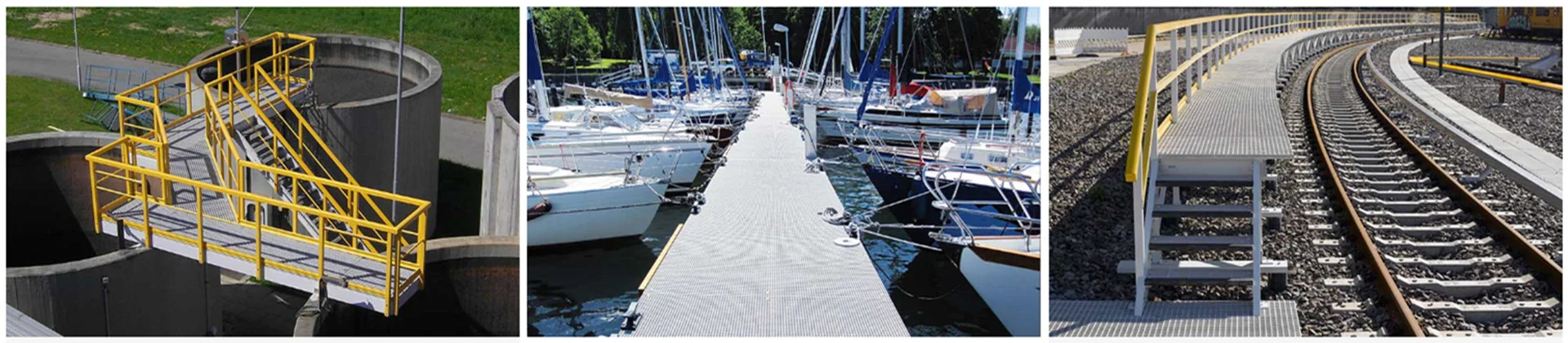
Hand layup’s real-world product range reveals why it remains indispensable alongside higher-automation FRP processes. Large storage tanks, chemical containment vessels, and equipment linings represent hand layup’s clearest industrial advantage — these components routinely exceed the size constraints of any closed-mold process and require geometry that no pultrusion die can produce.
Custom architectural cladding panels, equipment enclosures, and infrastructure retrofit components are similarly well-suited. In bridge repair and civil infrastructure applications, hand layup allows repair patches and overlay panels to be formed directly to the contour of the existing structure — a capability that pre-manufactured pultruded components cannot replicate without complex secondary fabrication.
In the most chemically aggressive service environments — where sustained exposure to acids, alkalis, or oxidizing media makes every potential ingress point a long-term risk — a continuous hand-laid laminate offers a relevant structural advantage. Even well-designed mechanical joints in pultruded assemblies introduce potential ingress points that a seamless hand-laid structure eliminates entirely. For standard corrosive industrial environments, well-specified pultruded assemblies perform reliably; for the most aggressive chemical immersion service, the seamless laminate removes a failure mode rather than managing it.
4.2 Marine and Transportation
Marine applications drove the early commercial adoption of hand layup, and the process remains the dominant manufacturing method for boat hulls, yacht decks, and marine superstructure components across a wide size range. The gel coat surface capability — applying a factory-finished outer resin layer before fiber layup — delivers a UV-stable, osmosis-resistant outer face without secondary painting or coating operations.
Vehicle body panels, truck fairings, custom transportation enclosures, and specialized vehicle components represent a parallel product category where hand layup’s combination of low tooling cost and complex geometry handling makes it the standard process for low-to-medium volume production runs.
4.3 Custom OEM and Prototype Parts
For OEM manufacturers and engineering teams specifying custom FRP components, hand layup’s most commercially valuable characteristic is the absence of a minimum order quantity. Single-piece prototype production is economically viable in a way that no tooling-intensive process can match — and the same mold can produce engineering validation samples, pilot-run quantities, and initial production batches without any process change.
In Unicomposite’s project experience, the most common transition pattern is hand layup for first-article and qualification samples, followed by a pultrusion die investment once the geometry is confirmed and annual volume crosses the economic threshold. Buyers who plan this transition from the outset — specifying a constant cross-section in the hand-laid prototype even where the mold could accommodate more geometric variation — avoid the tooling cost of redesigning the part for pultrusion later. A single conversation with the manufacturer at the prototype stage can determine whether the geometry is pultrusion-compatible, saving significant re-engineering cost down the line.
Unicomposite’s hand layup capability operates alongside its pultrusion and filament winding lines, which means buyers can source standard pultruded structural profiles and custom hand-laid enclosures or housings from a single supplier. Material compatibility across a mixed FRP assembly — same resin family, same fiber type — is easier to specify and verify when both components come from one manufacturer’s controlled process environment.

fiberglass hand layup vs high volume methods
5. Key Limitations Buyers Must Understand Before Specifying Hand Layup
The tooling cost, minimum order quantity, and design freedom advantages of hand layup are quantified in the process comparison table in Section 3 — the points below address limitations that the table cannot capture, and that directly affect specification decisions for structural and compliance-sensitive applications.
5.1 Laminate Quality Consistency
Fiber wet-out completeness, void content, and resin-to-glass ratio — the three variables that most directly determine mechanical performance — all depend on operator skill in hand layup in a way that pultrusion’s automated die environment does not. As noted in Section 1.2, void content ranges of 2–4% for experienced operators versus 8–12% for less experienced operators on identical molds and resin systems represent a meaningful mechanical performance difference that incoming dimensional inspection cannot detect.
Buyers should specify minimum quality criteria in the purchase order: maximum void content by percentage, minimum fiber weight per layer, and cure process log documentation as a delivery requirement. For structurally critical components, third-party incoming inspection using ultrasonic C-scan or destructive cross-section sampling on retained specimens provides the only reliable verification of internal laminate quality.
5.2 Fiber Volume Fraction Ceiling
Hand layup typically achieves fiber volume fractions of 25–40%, compared to 50–60% in pultrusion and 55–65% in filament winding. For applications where specific tensile or flexural strength targets must be met — structural members under defined load cases, pressure-rated components, or parts replacing steel or aluminum at reduced wall thickness — verify that the hand layup process can achieve the required mechanical properties before specifying it for high-load service. Request ASTM D638 (tensile) and ASTM D790 (flexural) test data for the specific laminate schedule and resin system you intend to specify.
5.3 Dimensional Repeatability
Hand-laid formed dimensions carry tolerances of approximately ±1–2 mm, compared to ±0.5 mm for pultruded profiles per ASTM D3917. For components where fit-up precision matters — connection interfaces, mating surfaces, or components that must align with pultruded structural members — account for this tolerance difference at the design stage. Secondary machining of hand-laid FRP is feasible but introduces an additional process step and cost; note that machined surfaces expose raw fiber ends that require sealing with resin coat in corrosive service environments.
5.4 Styrene Emission Compliance for Polyester Systems
Polyester and vinyl ester hand layup releases styrene monomer during the open-mold process. In North American manufacturing and construction environments, styrene emissions are subject to OSHA PEL limits (50 ppm TWA) and state-level regulations that may be more stringent. Buyers specifying hand layup FRP components manufactured domestically or evaluating supplier facilities for audit purposes should confirm that the supplier’s facility ventilation and personal protective equipment systems meet applicable occupational exposure standards. Epoxy-based hand layup does not involve styrene and does not carry this compliance consideration.
Conclusion
Fiberglass hand layup molding is not a fallback for when other processes are unavailable. It is the correct first choice for complex geometry, low-volume custom parts, and prototype development — and the wrong choice for high-volume standard profiles where pultrusion’s automation advantage dominates. Four takeaways for procurement decisions:
- Match the process to the geometry and volume. Complex shape at low quantity → hand layup. Constant cross-section at volume → pultrusion. Pressure-rated cylinder → filament winding. High-volume complex part → SMC. Defaulting to pultrusion for everything is a specification error, not a safe default.
- Specify the resin system explicitly. Polyester for cost-sensitive general applications. Vinyl ester for chemical or marine service. Epoxy for high-performance structural or bonded assemblies. Never specify “FRP” without a resin system — the performance difference is too large to leave undefined.
- Request cure process records, fiber weight documentation, and void content data. For hand layup, these are the quality verification equivalents of dimensional inspection reports for pultruded profiles. A supplier who cannot provide them cannot demonstrate process control.
- Plan the process transition before volume grows. Hand layup is the economically rational starting point for most custom FRP parts. If annual demand grows beyond 300–800 units and geometry is stable, evaluate pultrusion or SMC to capture the per-unit cost advantage of higher automation — and design the prototype with that transition in mind.
As OEM manufacturers and infrastructure operators expand FRP specification across more applications, the ability to select the right manufacturing process — not just the right material — becomes a core procurement competency that directly affects both cost and performance outcomes.
[Contact Unicomposite to discuss custom FRP parts via hand layup, pultrusion, or filament winding →]
Frequently Asked Questions
Hand layup imposes no minimum order quantity — single-piece prototype production is economically viable because open-mold tooling cost is low enough to amortize across a single part. For engineering validation samples, one-off replacement components, and initial prototype runs, hand layup is the correct process regardless of quantity. Lead time for a first-article hand-laid part typically runs 1–3 weeks from confirmed design, depending on mold fabrication requirements.
Provide the service environment details in your inquiry: the specific chemical media the part will contact, operating temperature range, whether exposure is immersion or splash, and any UV or outdoor weathering requirement. With this information, a multi-process manufacturer can recommend between polyester (general structural), vinyl ester (chemical or marine immersion), and epoxy (high-performance structural or bonded assemblies) — and confirm whether the resin system is compatible with the part geometry and layup schedule.
Yes. ASTM D638 (tensile strength) and ASTM D790 (flexural strength and modulus) test specimens can be fabricated from the same laminate schedule as the production part and tested by a third-party laboratory. Buyers should specify which standards apply in the purchase order, and request that the supplier retain test specimens from the same production batch as the delivered parts for potential arbitration testing. ISO 527 and ISO 178 are the equivalent standards for international project specifications.
Plan for ±1–2 mm on formed dimensions for hand-laid components, compared to ±0.5 mm for pultruded profiles per ASTM D3917. If the part must interface with pultruded structural members at tight fit-up, design the connection detail to accommodate the wider hand-layup tolerance — or specify secondary machining of the mating surface, with the understanding that machined edges in corrosive service require resin sealing. Communicate tolerance requirements at the inquiry stage so the manufacturer can advise on whether the specification is achievable without secondary operations.
Design the hand-laid prototype with pultrusion compatibility in mind if volume growth is anticipated: specify a constant cross-section where the geometry allows, and avoid features that require mold undercuts or compound curves that a pultrusion die cannot accommodate. Share your volume projections with the manufacturer at the prototype stage — a manufacturer running both hand layup and pultrusion lines can confirm whether the part geometry is pultrusion-compatible and estimate the die investment required, allowing you to make a transition decision based on actual cost data rather than assumptions.


