 info@unicomposite.com


A defective profile does not automatically mean that the pultrusion mold has failed. Treat the tooling as the confirmed source only after inspection connects the symptom to die damage, cavity condition, alignment, geometry or heating function. Until then, resin behavior, reinforcement delivery, preforming, pulling conditions and tooling condition remain competing possibilities.
The safest diagnostic sequence is simple: protect personnel, preserve the evidence, record the operating baseline, isolate the symptom by location, and change one controlled factor at a time. This prevents a process adjustment from hiding a damaged die—or an unnecessary die repair from masking a process problem.
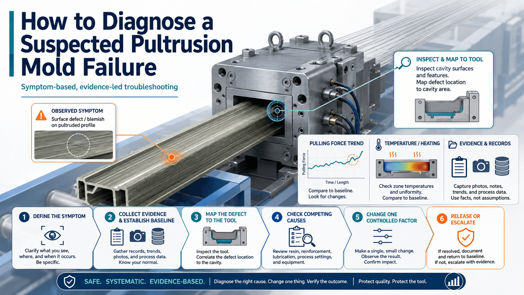
how to diagnose a suspected pultrusion mold failure
Stop First When the Condition Is Unsafe
Stop the line and follow the facility’s approved energy-control procedure before an inspection requires access to guarded areas, a die opening, removal of components or exposure to stored electrical, mechanical, hydraulic, pneumatic or thermal energy. OSHA 29 CFR 1910.147 requires hazardous energy to be controlled during covered servicing and maintenance activities.
Do not continue production or attempt an improvised repair when any of the following is present:
- a visible crack, chipped load-bearing feature or loose tooling component;
- unexpected die or support movement;
- a sharp and unexplained increase in pulling force;
- repeated reinforcement breakage with a risk of sudden release;
- damaged heaters, sensors, wiring or temperature-control components;
- a condition that cannot be inspected under the site’s approved safety procedure; or
- a critical cavity dimension that is outside the approved acceptance limit.
Grinding, polishing, welding, plating removal, localized heating or force-straightening can alter geometry, surface condition or material properties. These actions require an engineering repair plan, dimensional controls and authorization from the responsible tooling engineer.
How to Diagnose a Suspected Pultrusion Mold Failure
A practical diagnosis follows six stages:
- Stop the line and control hazardous energy where access is required.
- Preserve the affected profile, tooling condition and process records.
- Compare the event with the last accepted production baseline.
- Map the symptom to the profile, tooling and downstream equipment.
- Test one supported hypothesis at a time under controlled conditions.
- Release, repair, modify or replace the tool only against documented acceptance criteria.
This sequence separates observable evidence from assumptions. It also creates a record that another operator, quality inspector or tooling engineer can review without reconstructing the event from memory.
What Evidence Supports a Confirmed Pultrusion Mold Failure?
Evidence becomes stronger when the profile symptom maps to a verified tooling condition. Examples include:
- a repeatable defect at the same cavity, mandrel or insert location;
- tooling geometry or alignment outside its defined acceptance limit;
- a verified crack, chip, permanent deformation or surface-system failure;
- a mapped defect that remains after controlled cleaning; or
- a symptom that remains under the last accepted material and process conditions while other supported causes are eliminated.
A single profile defect, pulling-force increase or temperature change is not sufficient on its own. A confirmed tooling failure needs an observed condition, a location or measurement that connects it to the tool, and an acceptance criterion that the tooling no longer meets.
How to Diagnose Pultrusion Mold Failure by Symptom
Pultrusion behavior is coupled. Research on the process describes interactions among resin flow and pressure, heat transfer and cure, pulling force, shrinkage, stress and friction.23 Therefore, one symptom rarely proves one root cause. The following matrix is a diagnostic starting point, not a substitute for the mold drawing, process specification or site safety procedure.
| Observed symptom | Possible cause categories | Check in this order | Corrective-action boundary | Stop and escalate when |
|---|---|---|---|---|
| A repeatable longitudinal scratch, ridge or gloss change at the same profile location | Cavity contamination; localized surface damage; foreign material; reinforcement contact; cured buildup | Mark the defect position on the profile; map it to the cavity; inspect and document the matching die area; compare before and after controlled cleaning | Remove only verified contamination with the specified method; do not polish until geometry and surface requirements are known | The cavity has a groove, chip, peeling surface layer or measurable damage |
| Pulling force rises, oscillates or changes abruptly | Reinforcement crowding; preform misalignment; resin buildup; cure-location shift; surface friction; cavity or mandrel damage | Save the force trend; note when the change began; inspect material path and preform alignment; check buildup; compare temperature and line-speed records; inspect the mapped tooling area | Correct an identified setup or contamination issue one factor at a time; verify against the same recorded baseline | Force continues to rise, reinforcement breaks, the tool moves, or structural damage is suspected |
| Resin accumulates at the entrance or the profile sticks | Excess resin delivery; poor material distribution; entry restriction; contamination; release-system change; cure starting in the wrong location | Identify where buildup begins; compare resin batch and formulation records; inspect reinforcement distribution and entry condition; review the temperature profile | Restore the approved material path or cleaning condition; process changes require controlled trials | Buildup returns immediately, damages the surface or coincides with abnormal force |
| Wall thickness, flatness or profile dimensions drift | Reinforcement displacement; mandrel or insert movement; die alignment; thermal nonuniformity; cavity wear or deformation | Confirm the measurement system; compare the defect location with reinforcement and tooling geometry; check supports, fasteners and alignment; inspect cavity and mandrel dimensions | Correct verified setup errors under the approved procedure; re-machine only to an engineering disposition | A critical tool dimension is out of tolerance or a component has shifted or deformed |
| Under-cure, over-cure, cracking or surface condition changes with a temperature-zone pattern | Heater or sensor issue; cure-location shift; line-speed change; resin-system change; poor thermal contact | Verify sensors and actual zone response; compare temperature, speed, resin and defect-location records; separate thermal evidence from surface-damage evidence | Use a controlled process trial only after instrumentation and tooling condition are verified | Electrical damage, uncontrolled heating or an unexplained hot spot is present |
| Visible crack, chipping, permanent deformation or fractured feature | Overload event; impact; stress concentration; support or alignment issue; material or heat-treatment problem; accumulated damage | Stop; photograph and map the damage; preserve fragments; review recent events and maintenance history; inspect adjacent features and supports; measure against the drawing | No production repair without engineering disposition, repair scope and reinspection criteria | Always escalate before reuse |
| Pitting, corrosion or coating deterioration | Chemical exposure; cleaning incompatibility; moisture during storage; coating damage; wear | Record location and extent; review resin and cleaning-agent exposure; inspect storage history; compare with the specified surface system | Isolate the exposure source; obtain a repair or recoating specification before altering the surface | The condition affects the cavity, dimensions, adhesion of a surface layer or profile finish |
Record the Baseline Before Changing the Process
A useful troubleshooting record connects the symptom to a time, position and operating state. Capture the following before adjustments erase the evidence:
- die identification and drawing revision;
- profile identification and critical inspection result;
- defect location on the profile and corresponding cavity location;
- pulling-force trend, not only a single reading;
- line speed and actual temperature-zone response;
- resin system, batch or formulation change record;
- reinforcement package, material path and preform arrangement;
- start-up, steady-state or post-interruption condition;
- recent cleaning, adjustment, impact or maintenance activity; and
- clear photographs of the profile and accessible tooling surfaces.
Use the last accepted production condition as the comparison point. If several inputs changed at once, return to a documented state where safe and practical, then test one hypothesis at a time. Record the change, the conditions held constant and the acceptance result.
Diagnose Repeating Surface Marks by Location
A surface line that repeats at one fixed position is useful evidence because it can be mapped from the profile back to the die cavity, mandrel or insert. First confirm that the mark is not created downstream by a puller, guide or cutoff operation. Then inspect the corresponding tooling location for cured resin, embedded debris, a scratch, edge damage or deterioration of the specified surface system.
Controlled cleaning may distinguish removable buildup from permanent damage. If the mark remains after cleaning, document its length, direction and location and compare the cavity with the controlled drawing and surface acceptance criteria. Do not blend or polish the area simply because the defect appears shallow; material removal can change a critical dimension or create a local transition that produces another mark.
Routine cleaning, inspection and storage belong in the separate pultrusion mold maintenance procedure. This page addresses the point at which an observed condition requires diagnosis rather than scheduled care.
What Causes Pulling Force to Rise?
Pulling force is a valuable trend, but it is not a root-cause label. Experimental and modeling work links pull force to compaction, resin state, temperature, pulling speed, reinforcement configuration, shrinkage and friction.23 Die-entry pressure also changes with pull speed, resin viscosity, fiber volume and entry geometry.4
When force begins to rise or oscillate:
- Preserve the time-series data and mark the start of the change.
- Check whether a resin, reinforcement, speed, temperature or setup change occurred at the same time.
- Inspect reinforcement delivery for crowding, twisting, breakage or an altered preform path.
- Look for buildup at the entrance and for a defect location that maps to a cavity or mandrel feature.
- Compare actual temperature response—not only controller setpoints—with the last accepted run.
- Make one controlled correction and verify both the pulling-force trend and the trial profile under documented conditions.
Do not compensate for unexplained high force by increasing pulling capacity. That can conceal a restriction or damaged feature while increasing the consequence of a jam or sudden release.
Separate Resin Buildup From Premature Cure and Entry Restriction
Resin at the die entrance may reflect excess delivery, reinforcement distribution, entry geometry, contamination or a cure location that has shifted upstream. The location and timing of the buildup help separate these possibilities.
- Buildup starts immediately after a material or setup change: compare the resin record, reinforcement package and preform path first.
- Buildup increases as the run warms: compare actual zone response, line speed and resin behavior over time.
- Buildup is concentrated at one feature: map it to local reinforcement crowding, an insert, mandrel or entry transition.
- Cleaning gives only short-lived improvement: preserve the recurrence interval and inspect for a geometry, surface or process cause instead of repeating more aggressive cleaning.
Temperature and cure diagnosis should be handled on the dedicated guide to die temperature and curing conditions. Avoid copying a temperature or speed from another profile: the resin system, reinforcement package, cross-section, die design and production conditions determine whether it is relevant.
Trace Dimensional Drift to Measurement, Material Path or Tooling
Confirm the measurement before changing the mold. Use the approved inspection method, sampling location and stabilized part condition. Then determine whether the dimensional change is constant, progressive, intermittent or linked to one position in the cross-section.
A constant offset can point toward setup, alignment, insert position or a measurement issue. Progressive drift can justify checking thermal behavior, support movement, buildup or wear. An intermittent change may follow reinforcement distribution, process interruptions or unstable operating conditions. These are investigation routes, not confirmed diagnoses.
If a mandrel, insert, split line or support appears to have moved, stop and compare its position with the controlled tooling drawing. If the cavity or component is outside its acceptance limit, engineering must define whether adjustment, repair, re-machining or replacement is appropriate and how the result will be inspected.

pultrusion mould failure
Classify Visible Tool Damage Without Guessing the Mechanism
Visible tooling damage can be described accurately before its metallurgical cause is known:
- Permanent deformation: a cavity, edge, insert or support no longer matches its approved geometry.
- Wear or surface loss: material or a specified surface layer has been removed, rounded, scored or locally deteriorated.
- Cracking: a linear discontinuity is visible or detected by an approved inspection method.
- Chipping or fracture: a portion of a feature has separated or broken.
Do not label a crack as fatigue, overload, embrittlement or heat-treatment failure from appearance alone. Confirming the mechanism may require dimensional inspection, event history, material records and an appropriate examination method. Preserve fragments and photographs, and avoid altering the fracture or crack surface before the responsible engineer decides what evidence is needed.
Choose Corrective Action by Evidence Level
Use the least invasive action that addresses a verified cause and produces a measurable acceptance result:
- Process or setup correction: appropriate when records and inspection identify a material-path, operating or instrumentation issue and the tooling remains within acceptance criteria.
- Specified cleaning: appropriate for verified removable contamination when the method is compatible with the specified tooling surface.
- Controlled adjustment: appropriate for an adjustable support, insert or alignment feature when the drawing and procedure define the target and verification method.
- Engineered repair: required when material removal, welding, recoating, re-machining or replacement of a tooling component is proposed.
- Tool modification or replacement: appropriate when damage cannot be restored within the approved geometry and surface requirements, or when repeated failure points to a design or application mismatch.
Every correction needs a closure record: the symptom, confirmed or most-supported cause, action taken, conditions held constant, inspection result, trial condition and release authorization. If the evidence does not support a root cause, record the open hypotheses instead of converting an assumption into a permanent maintenance instruction.
Prevent Recurrence With Trend-Based Controls
Prevention is stronger when it monitors changes from an accepted baseline rather than relying only on calendar intervals.
- Trend pulling force and investigate meaningful changes under comparable operating conditions.
- Map repeated profile defects to cavity locations and keep photographs with the die record.
- Record resin, reinforcement, speed and temperature changes with each production run.
- Inspect high-contact and transition areas using consistent lighting, cleanliness and acceptance criteria.
- Protect cavity surfaces during cleaning, handling and storage.
- Verify heater and sensor response when the defect follows a thermal pattern.
- Require engineering disposition for cracks, chips, deformation, dimensional loss or surface-system failure.
- Review the failure record after corrective action and update the inspection plan only with verified findings.
Pultrusion Mold Failure Checklist
Before restarting the line, confirm that the team can answer each question:
- What exact symptom triggered the investigation?
- Where and when did it occur?
- Was hazardous energy controlled under the approved procedure?
- Which process and material records were preserved?
- Was the profile symptom mapped to the tooling or downstream equipment?
- Which possible causes were checked, and what evidence eliminated each one?
- Was only one controlled factor changed at a time?
- Does the tooling still meet the drawing and surface acceptance criteria?
- What inspection and trial results support release?
- Who authorized the restart?
Frequently Asked Questions
Does high pulling force prove that a pultrusion mold is damaged?
No. High or unstable pulling force can be associated with reinforcement compaction, resin state, cure location, temperature, speed, friction, buildup or tooling damage. Preserve the trend, compare it with the last accepted run and inspect the material path and tooling before assigning a root cause.
Can a scratched pultrusion die be polished during production troubleshooting?
Not without an engineering repair plan. Polishing removes material and can change dimensions, transitions and the specified surface condition. First map the profile mark to the cavity, remove only verified contamination using the specified method, and have permanent damage evaluated against the drawing and acceptance criteria.
When should a pultrusion mold be repaired or replaced?
Engineering review is required when cracks, chipping, permanent deformation, dimensional loss or surface-system failure prevents the tooling from meeting its approved geometry and surface requirements. The review should define whether repair, component replacement, modification or a new tool is appropriate, together with inspection and trial acceptance criteria.
When Does a Pultrusion Die Need Repair or Replacement?
If inspection shows that the die cannot be returned to its approved geometry or surface condition through an authorized repair, prepare the evidence before requesting a tooling review. Include the profile drawing, critical tolerances, photographs and measured location of the damage, resin information, reinforcement plan, operating records, failure history and acceptance requirements.
Review our pultrusion molds and tooling range, or send us your profile drawing, critical tolerances, resin information, reinforcement plan, target production conditions, documented failure evidence and acceptance requirements for an initial project discussion. Tool material, surface treatment, modification scope, trial conditions and commercial terms can then be confirmed during engineering review and quotation.
References
- Occupational Safety and Health Administration. 29 CFR 1910.147—The Control of Hazardous Energy (Lockout/Tagout).
- Safonov, A. A., Carlone, P., and Akhatov, I. “Mathematical Simulation of Pultrusion Processes: A Review.” Composite Structures, 184 (2018): 153–177. https://doi.org/10.1016/j.compstruct.2017.09.093.
- Mukherji, A., and Njuguna, J. “An Assessment on Effect of Process Parameters on Pull Force During Pultrusion.” The International Journal of Advanced Manufacturing Technology, 121 (2022): 3419–3438. https://doi.org/10.1007/s00170-022-09221-0.
- Sharma, D., McCarty, T. A., Roux, J. A., and Vaughan, J. G. “Investigation of Dynamic Pressure Behavior in a Pultrusion Die.” Journal of Composite Materials, 32(10) (1998): 929–950. https://doi.org/10.1177/002199839803201002.


