 info@unicomposite.com


Introduction
Steel conduit in AC power distribution environments does two things that FRP conduit does not: it conducts electricity, and it corrodes. The conductivity problem generates eddy currents in steel conduit walls when alternating magnetic fields from current-carrying cables induce circulating currents in the conductive metal — producing heat, measurable energy loss, and accelerated cable insulation degradation. The corrosion problem is more familiar: buried steel conduit in humid soil begins losing coating integrity within 5–7 years, initiating electrolytic corrosion that, based on infrastructure inspection records from coastal and industrially contaminated buried conduit installations, produces active section loss within 8–12 years of installation.
FRP cable protection pipe eliminates both failure modes at the material level. The performance data and application guidance in this article draw on FRP cable protection pipe design and supply experience spanning urban power distribution, HV single-core cable laying, and bridge and river crossing infrastructure applications, developed through conduit system production for utility and telecommunications B2B customers in North American and international markets. It gives utility engineers and procurement managers a technical framework for specifying FRP cable protection pipe — covering material construction, performance properties, installation system mechanics, material comparison, and application fit across power distribution, telecommunications, and infrastructure cable crossing projects.

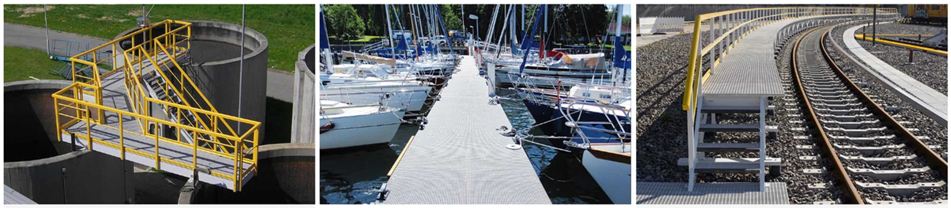
frp cable protection pipe
What Is FRP Cable Protection Pipe? Material and Manufacturing Basis
Understanding why FRP cable protection pipe outperforms PVC and steel in high-performance underground cable infrastructure begins with understanding what it is made of and how the manufacturing process determines its performance consistency.
Material Composition: Pultruded Fiberglass and Resin Matrix
FRP cable protection pipe is produced by pultrusion — a continuous manufacturing process that pulls glass fiber rovings through a resin bath and then through a heated die, aligning fiber reinforcement longitudinally through the pipe wall at consistent fiber volume fraction and wall thickness. The thermosetting resin matrix — typically polyester for standard utility service or vinyl ester for chemical exposure and elevated temperature applications — binds the fiber system and provides chemical inertness and electrical non-conductivity.
The weight result of FRP construction is operationally significant. FRP cable protection pipe weighs approximately 25% of equivalent steel conduit at the same bore size — enabling one-person carry and two-person installation in standard trench configurations, without the lifting equipment that steel conduit handling requires in deep trench and confined access sites.
Pultrusion’s dimensional consistency is critical for socket-joint conduit systems. Every pipe length off the same die produces the same outer diameter, wall thickness, and socket geometry — which means joint assembly requires no field machining, no tolerance adjustment, and no field rejection of mismatched pipe ends. Dimensional scatter from alternative manufacturing methods introduces socket-joint leak risk that pultruded FRP eliminates by process control.
Why FRP Replaces PVC and Steel in High-Performance Cable Infrastructure
PVC conduit dominates in low-current telecommunications and signal cable applications because it is lightweight, inexpensive, and easy to cut and join. Its limitation is temperature: PVC softens at 60–80°C continuous service temperature — a ceiling that high-current power cable installations routinely exceed when cable surface temperature and soil thermal resistance combine to elevate conduit ambient above the PVC limit. FRP cable protection pipe is rated for 130°C continuous service without deformation, covering the full temperature range of power distribution cable applications.
Steel conduit’s limitation is conductivity. In AC power environments, steel conduit walls carrying single-core high-voltage cable generate eddy currents from the alternating magnetic field of the cable conductor — producing resistive heating in the conduit wall and creating a return current path that, in buried installations with imperfect coating, initiates electrolytic corrosion at coating breach sites. These are not coating-dependent failure modes in FRP: the glass fiber and thermosetting resin matrix are non-conductive through their full wall thickness, so there is no eddy current generation pathway and no electrolytic corrosion mechanism regardless of coating condition or service age.
Engineers who have reviewed cable system performance records from long-operating underground power networks consistently note that the transition from steel to FRP conduit in single-core HV cable laying programs follows a recurring pattern: first specification driven by regulatory compliance, then confirmed by cable insulation service life improvement data from comparative installations on the same network.
Key Performance Specifications
Seven performance properties differentiate FRP cable protection pipe from PVC and steel conduit in the underground utility environments where cable infrastructure must perform for 30+ years without maintenance. Each property addresses a specific failure mode or regulatory requirement that drives the specification decision.
The table below summarizes the key performance specifications of pultruded FRP cable protection pipe relevant to utility and infrastructure B2B procurement:
| Property | FRP Cable Protection Pipe | Standard Value / Range | Operational Significance |
|---|---|---|---|
| Continuous Service Temperature | 130°C | No deformation at rated temperature | Covers high-current power cable ambient temperature range |
| Electrical Conductivity | Non-conductive | Full wall cross-section | No eddy current; no electrolytic corrosion |
| Flame Rating | Flame retardant | FH-1 or equivalent | Required for underground cable tunnel fire safety |
| Mechanical Strength (buried) | High — external pressure rated per ASTM D2412 | Direct burial under driveways without encasement | No concrete cover required under standard traffic loading |
| Inner Surface Roughness | Low — Ra ≤ 3.2 µm | From pultruded die surface | Lower friction than steel seam welds; longer single-pull cable distances |
| Corrosion Resistance | Excellent | Inert to soil chemistry, salinity, acid | 30+ year service life in buried environment |
| Weight vs. Steel | ~25% | Application-dependent | Single-person carry; reduced installation labor |
Electrical Insulation: No Eddy Current, No Electrolytic Corrosion
In AC power distribution cable systems, the alternating magnetic field generated by current-carrying conductors induces eddy currents in any electrically conductive material in proximity — including the walls of steel conduit enclosing the cable. These induced currents generate resistive heat in the conduit wall, representing a continuous energy loss that adds to the cable system’s operating cost and accelerates cable insulation aging through elevated ambient temperature inside the conduit.
The electrolytic corrosion mechanism is a secondary consequence of steel conduit conductivity in buried installations. Where coating damage creates a direct contact path between the steel conduit and the surrounding soil electrolyte, current flow from the cable’s induced field drives electrochemical corrosion at the steel surface. In salt-containing or acidic soil conditions — coastal sites, industrial contaminated ground, and chemically active fill — this process is accelerated well beyond the rates observed in neutral soil.
FRP cable protection pipe generates zero eddy current and zero electrolytic corrosion — not reduced levels, but zero. The glass fiber and resin matrix have no free electrons to carry induced current, and no metal surface to oxidize. This is the property that most consistently drives FRP specification in single-core high-voltage cable laying programs across utility infrastructure markets.
Flame Retardancy and Heat Resistance: 130°C Continuous Rating
Flame retardant FRP cable protection pipe satisfies FH-1 or equivalent fire classification requirements for underground cable tunnel installations where fire containment between cable zones is a safety and regulatory design requirement. This rating means the conduit self-extinguishes after the ignition source is removed and does not propagate flame along the cable route — a critical property in dense conduit bank installations where a single ignition event could affect multiple cable circuits simultaneously.
The 130°C continuous service temperature rating is the specification parameter that most directly differentiates FRP from PVC in power distribution applications. High-current distribution cables — particularly when loaded at or near their rated ampacity in summer ambient conditions — generate cable surface temperatures that can elevate conduit ambient to 80–100°C in thermally resistive soil. PVC begins to soften at its 60–80°C service ceiling under these conditions, increasing the risk of conduit deformation and cable jacket contact with the conduit wall.
Mechanical Strength: Road Traffic Load and Settlement Flexibility
FRP cable protection pipe achieves sufficient external pressure resistance for direct burial under driveways and lightly trafficked roads without concrete encasement — tested per ASTM D2412 or equivalent conduit crushing load standard. Buyers should request the load class test certificate confirming direct burial capability under the specific traffic loading condition of their installation, not simply rely on a material category description.
FRP composite also exhibits elastic deformation behavior under external pressure — the pipe wall deflects under load and recovers rather than fracturing, which is the failure mode PVC conduit exhibits under differential settlement. In sites with variable soil bearing capacity or anticipated ground movement — coastal reclaimed land, sites near excavation, and areas with high seasonal water table variation — FRP’s elastic recovery maintains conduit bore integrity where rigid materials develop permanent oval deformation that impedes cable pulling.
Installation System: Socket Connection, Rubber Seal, and Conduit Bank Assembly
Beyond material properties, the installation system design determines whether FRP cable protection pipe delivers its rated performance in the field. The socket-and-spigot joint, rubber seal, smooth inner surface, and pipe pillow spacer system each address specific installation quality risks.
Socket-and-Spigot Joint Design: Thermal Expansion and Watertight Performance
The socket-and-spigot joint system connects adjacent pipe lengths by sliding the plain spigot end of one pipe into the socket of the next, with a rubber seal ring seated at the socket throat providing the watertight and mud-proof seal. No adhesive, solvent cement, or mechanical fastener is required — the rubber seal provides joint integrity and accommodates the differential thermal expansion between adjacent pipe lengths that buried conduit systems experience through seasonal temperature cycling.
In one urban power distribution cable laying project on a four-lane arterial road where the road authority imposed per-day penalties for trench open time beyond 48 hours, installation teams replacing a scheduled 80-joint steel threaded conduit section with FRP socket-joint conduit completed the conduit run in 55–65% of the projected steel installation time — reducing the total trench open period from a projected 3.5 days to 2 days and avoiding the penalty threshold entirely. The time saving came from two sources: the absence of thread engagement and torque verification at each joint, and the elimination of the thread lubrication and seal tape application that steel couplings require.
The rubber seal also prevents sand and mud infiltration at pipe joints — a critical function in water table conditions where trench dewatering is imperfect and fine sediment migrates under hydrostatic pressure into any unsealed joint gap. FRP socket joints with rubber seals maintain cable pulling clearance through the conduit bore; inadequately sealed steel conduit joints allow sediment ingress that requires bore cleaning before cable pulling operations can proceed.
Smooth Inner Surface: Cable Pull-Through Protection
FRP cable protection pipe inner surface roughness — typically Ra ≤ 3.2 µm from the pultruded die surface — produces lower cable jacket-to-conduit friction than steel conduit seam welds, enabling longer single-pull cable installation distances within cable manufacturer installation tension limits. Pull-through tension is a critical parameter in long conduit runs: the cumulative friction between cable jacket and conduit inner surface over hundreds of meters of pull directly determines whether cable can be installed without exceeding the manufacturer’s maximum tension specification.
Steel conduit inner surfaces carry longitudinal seam welds in welded pipe and thread engagement ridges in threaded-and-coupled conduit — both of which create localized stress concentration points on the cable jacket during pull-through. In cable types with sensitive outer jackets — particularly XLPE-insulated HV cables where outer jacket scoring creates moisture ingress pathways — this contact damage initiates long-term cable performance degradation that does not manifest until years into service.
Multi-Layer, Multi-Column Conduit Bank with Pipe Pillow Spacers
FRP cable protection pipe systems include compatible pipe pillow spacers — preformed composite supports that position individual conduit pipes at specified centre-to-centre spacings in multi-layer, multi-column conduit bank configurations. Standard configurations support two- and three-column banks at single and double-tier vertical arrangements, covering the cable quantity ranges required for urban power distribution and telecommunications cable routes.
The conduit bank geometry — specifically the spacing between individual conduit centrelines — directly affects cable heat dissipation and current capacity derating, and requires engineering calculation before the pipe pillow spacer specification is finalized. Engineers specifying FRP conduit bank configurations for high-load power distribution routes should calculate the thermal resistance of the conduit bank based on soil thermal resistivity, cable loading, and centre-to-centre spacing. Under-spacing conduit in high-density cable banks reduces per-cable current capacity below the design rating — a condition that manifests as unexpected cable temperature exceedance during peak load periods and requires either cable de-rating or conduit bank modification after installation.

engineered for utility infrastructure
FRP Cable Protection Pipe vs. PVC vs. Steel: Full Specification Comparison
The specification conditions identified across the performance sections above — service temperature above 80°C, single-core HV cable non-conductivity requirements, and corrosive buried environments — each map to a specific procurement decision point where FRP’s advantages are operationally decisive rather than merely preferable. The comparison below covers seven dimensions where the three materials diverge most significantly.
The table below compares FRP cable protection pipe, PVC conduit, and steel conduit across the key specification dimensions for utility and infrastructure B2B procurement decisions:
| Specification Dimension | FRP Cable Protection Pipe | PVC Conduit | Steel Conduit |
|---|---|---|---|
| Continuous Service Temp. | 130°C | 60–80°C | 200°C+ |
| Electrical Conductivity | Non-conductive | Non-conductive | Conductive — eddy current and electrolytic corrosion |
| Flame Rating | FH-1 flame retardant | Variable — not all grades flame rated | Non-combustible |
| Mechanical Strength (buried) | High — direct burial under roads per ASTM D2412 | Moderate — concrete encasement required under roads | High — direct burial |
| Corrosion Resistance | Excellent — no coating required | Good — UV degradation at surface | Poor — coating required; electrolytic corrosion in buried |
| Weight vs. Steel | ~25% | ~12% | Baseline |
| Total Lifecycle Cost (30-year buried service) | Lowest — no maintenance | Medium — temperature limitation risk | Highest — corrosion inspection and replacement |
When PVC Is Sufficient and When FRP Is Required
PVC conduit is appropriate for low-current telecommunications, signal cable, and control cable applications where cable surface temperature remains below the PVC service ceiling, electrical non-conductivity is not a primary specification driver, and mechanical loading allows concrete encasement under road crossings. In these conditions, PVC’s lower unit cost and ease of handling justify its selection.
FRP becomes the required specification — not the preferred specification — in three conditions: service temperature above 80°C from high-current cable loading, single-core high-voltage AC cable laying where non-conductive conduit is a regulatory requirement, and buried environments where steel conduit corrosion would require inspection or replacement within the design service life. Identifying which of these conditions applies at the project specification stage — not at the conduit delivery stage — is the procurement discipline that prevents specification regret.
Lifecycle Cost: Maintenance-Free FRP vs. Steel Corrosion and Replacement Cycles
Steel conduit in buried utility environments begins losing coating integrity through abrasion during installation, differential settlement at pipe joints, and electrochemical reaction with soil moisture. Based on infrastructure inspection records from coastal and industrially contaminated buried conduit installations, active corrosion at steel conduit surfaces has been documented within 8–12 years of installation — initiating a remediation cycle that requires either conduit section replacement or cable rerouting, both of which require re-excavation and traffic management on completed road surfaces.
Unicomposite Technology Co., Ltd. — an ISO 9001-certified FRP manufacturer operating an 18,000 m² production facility in Nanjing — supplies pultruded FRP cable protection pipe to power utility, telecommunications, and civil infrastructure B2B customers in North American and international markets. Standard and custom bore configurations across polyester and vinyl ester resin systems are supported with load, dielectric, and flame certification documentation for utility infrastructure procurement programs.
The 30-year lifecycle cost of FRP cable protection pipe in corrosive buried environments consistently favors FRP over steel when excavation cost, traffic management, and cable replacement risk are included in the comparison — even in markets where steel conduit unit price is significantly below FRP.
Application Scenarios: Where FRP Cable Protection Pipe Performs Best
The specification conditions established in the comparison above translate into clear operational outcomes in three application environments where FRP’s non-conductivity, temperature rating, and corrosion immunity are decisive.
Urban Underground Power Distribution: Road Crossing and Direct Burial
Urban power distribution cable routes typically require conduit installation under existing road surfaces, with the conduit bank assembled in open-cut trenches that must be backfilled and reinstated within project time windows. FRP cable protection pipe’s direct burial capability — without the concrete haunching that PVC installations under roads require — reduces trench depth, excavation volume, and reinstatement time on urban road crossing projects where road authority time penalties apply.
In conduit bank configurations for urban power distribution, the multi-layer, multi-column assembly with pipe pillow spacers allows standardized bore spacing that simplifies cable pulling operations and future cable replacement — both critical factors on routes where cable replacement would require re-excavation of completed road surface.
High-Voltage Single-Core Cable Laying
Single-core high-voltage cable laying is the application where FRP’s non-conductivity specification is most directly mandated. AC power systems using single-core cables — the standard configuration for 66 kV and above transmission and primary distribution — generate asymmetric magnetic fields that induce sheath currents in any conductive material enclosing the cable. Non-conductive FRP conduit eliminates both the eddy current heating and the induced voltage on the conduit wall that steel conduit generates in these installations.
In one 132 kV single-core cable laying program where the original specification used steel conduit for a 1.2-kilometer urban cable route, thermal monitoring installed on the replacement FRP conduit section showed conduit ambient temperatures 8–12°C lower than the steel section at equivalent cable loading — consistent with the elimination of eddy current heating in the FRP wall. The thermal reduction allowed the cable section to operate closer to rated ampacity during peak demand periods without triggering the thermal protection setpoints that had required the steel conduit section to be de-rated. Unicomposite’s FRP cable protection pipe supply program for HV cable conduit applications covers 66 kV through 220 kV cable protection specifications, with bore size and wall thickness confirmed against the cable outer diameter and burial depth at the inquiry stage.
Bridge Crossing, River Crossing, and Special Environment Applications
Bridge cable chambers and cross-river conduit runs expose cable protection pipe to conditions that neither PVC nor steel handles reliably over a 30-year service life: continuous high humidity, splash zone salt exposure in coastal bridge environments, and potential submersion in river crossing applications. FRP’s corrosion immunity in salt water and humid environments — without coating maintenance — makes it the specification of choice for these environments where conduit access for inspection and replacement would require bridge lane closures or underwater work.
Telecommunications cable crossing applications in bridge and river environments additionally specify FRP for its dimensional stability under the thermal cycling that exposed bridge structures experience. Steel conduit expansion and contraction under daily and seasonal temperature variation generates mechanical stress at conduit-to-structure connection points that requires periodic re-tensioning that FRP’s lower thermal expansion coefficient significantly reduces.
Custom Specification and B2B Procurement
The FRP cable protection pipe system’s adaptability — in bore size, wall thickness, resin system, and conduit bank configuration — is what makes it applicable across the full range of power utility, telecommunications, and infrastructure cable protection requirements.
Diameter, Wall Thickness, and Length Options
Standard FRP cable protection pipe production covers inner diameters from 50 mm through 200 mm in common power and telecommunications cable protection sizes, with wall thickness determined by burial depth, soil loading, and traffic load class rather than from a fixed catalog. Provide the required inner diameter, burial depth, surface loading classification (pedestrian, light vehicle, heavy traffic), and soil type at inquiry — wall thickness is confirmed by structural calculation against ASTM D2412 or an equivalent load standard, not catalog selection.
Cut-to-length capability allows non-standard trench geometry to be accommodated without field cutting and end-sealing, which simplifies installation in locations where conduit runs must terminate at precise cable pull-pit positions.
Resin System Selection and Certification Documentation
Polyester resin covers standard power utility and telecommunications conduit applications at ambient to moderate service temperatures in standard soil chemistry. Vinyl ester is specified for elevated temperature service above 100°C, chemical exposure in industrial contaminated ground, or high-salinity coastal environments where polyester resin’s chemical resistance ceiling is approached within the design service life.
Available certification documentation includes flame rating test records (FH-1 or equivalent), dielectric strength certificates, external load test data confirming direct burial capability per ASTM D2412, and ISO 9001 manufacturing certification covering the full production process. Standard bore and wall thickness configurations from existing production tooling ship within 3–5 weeks from order confirmation, based on standard production scheduling — confirmed timing is provided at inquiry. Custom bore sizes or specialty resin systems extend lead time to 6–8 weeks from specification sign-off.
Conclusion
FRP cable protection pipe earns its specification in underground utility infrastructure through four operational advantages that determine total installation cost and long-term cable system reliability:
- Non-conductivity eliminates regulatory and performance barriers in HV cable laying: Single-core high-voltage AC cable regulations mandate non-conductive conduit in most utility jurisdictions — FRP satisfies this requirement inherently, without coating maintenance or periodic insulation testing. Thermal monitoring in documented HV cable laying programs shows 8–12°C conduit ambient temperature reduction after steel-to-FRP transition at equivalent cable loading, confirming the eddy current elimination translates to measurable cable system thermal benefit.
- 130°C service temperature covers the full power distribution operating range: FRP’s thermal rating covers the conduit ambient temperature produced by high-current distribution cable loading in thermally resistive buried soil — the service condition where PVC conduit reaches its performance ceiling and creates cable system reliability risk.
- In ROW-restricted urban environments where road authority trench open time penalties apply, socket-joint FRP conduit’s installation speed advantage directly reduces project cost: The 55–65% joint completion time reduction versus steel threaded couplings is a procurement factor that belongs in the project cost comparison — not just the material specification comparison.
- Calculate lifecycle cost over the design service horizon, not unit conduit price: When excavation, traffic management, and cable replacement risk are included in the 30-year ownership cost comparison in corrosive and electrically sensitive buried environments, FRP’s higher unit price is typically recovered within the first avoided corrosion remediation cycle — at 8–12 years in coastal and industrial sites based on documented infrastructure inspection records.
[Contact Unicomposite — ISO 9001-certified FRP cable protection pipe manufacturer with custom bore and resin system engineering support — with your cable voltage class, burial depth, conduit bank configuration, and quantity to receive a specification and supply proposal →]
Frequently Asked Questions
Single-core HV cable carrying AC current generates an asymmetric alternating magnetic field that induces eddy currents and sheath voltages in any electrically conductive enclosing conduit — creating heat, energy loss, and induced voltage hazard on the conduit surface. Steel conduit is conductive and produces all three effects. FRP is non-conductive through its full wall cross-section, eliminating eddy current generation and induced voltage entirely. PVC is also non-conductive but does not meet the service temperature requirement for high-current HV cable installations. Most utility jurisdictions mandate non-conductive conduit for single-core cable above a specified voltage class — confirm the applicable regulatory requirement at the project specification stage.
Pultruded FRP cable protection pipe achieves 130°C continuous service temperature without deformation — approximately twice the service ceiling of standard PVC conduit, which softens at 60–80°C under sustained load. The FRP temperature rating covers the full range of power distribution cable ambient conditions, including high-current loading in thermally resistive soil during summer peak demand periods where conduit ambient can reach 80–100°C. Vinyl ester resin formulations extend the service temperature further for specialized applications above 100°C.
The rubber seal ring seated at the socket throat compresses against the spigot outer surface when the joint is assembled, creating a watertight and mud-proof seal without adhesive, solvent cement, or mechanical fastener. The rubber seal accommodates thermal expansion and contraction cycling and differential settlement between adjacent pipe sections without losing seal integrity. Field assembly requires no tooling beyond inserting the spigot end into the socket to the reference mark — joint completion time runs 55–65% faster than steel threaded coupling assembly in documented installation programs.
Standard documentation includes flame rating test records (FH-1 or equivalent), dielectric strength certificates, external load test data confirming direct burial capability per ASTM D2412, and ISO 9001 manufacturing certification. Specify required certification standards and acceptance criteria at inquiry to ensure documentation matches the project’s quality and regulatory requirements. Unicomposite provides test documentation upon request — confirm the required standard before order placement.
Provide: required inner diameter (cable outer diameter plus clearance), burial depth, surface loading classification (pedestrian, light vehicle, or heavy traffic road), soil type and groundwater conditions, cable voltage class, conduit bank configuration (single pipe, multi-column, number of tiers), project quantity and delivery location, and any required certification standards. This data allows wall thickness confirmation by structural calculation and resin system selection confirmation against the service temperature and chemical exposure conditions — both of which must be confirmed before production begins, not after delivery.


