 info@unicomposite.com



Pultrusion die manufacturing is not complete when the cavity has been machined. A production-ready die must connect a controlled design definition, a suitable manufacturing plan, finished forming surfaces, aligned tooling interfaces, fit-for-purpose inspection and documented acceptance criteria.
For buyers, the most useful question is not simply, “Was the die CNC machined?” It is, “What requirements were released, how were critical characteristics verified, and what evidence will be supplied before the tool is accepted?” The exact machines, materials, surface treatments and inspection methods vary by profile and project, so no single manufacturing sequence or universal tolerance table applies to every pultrusion die.
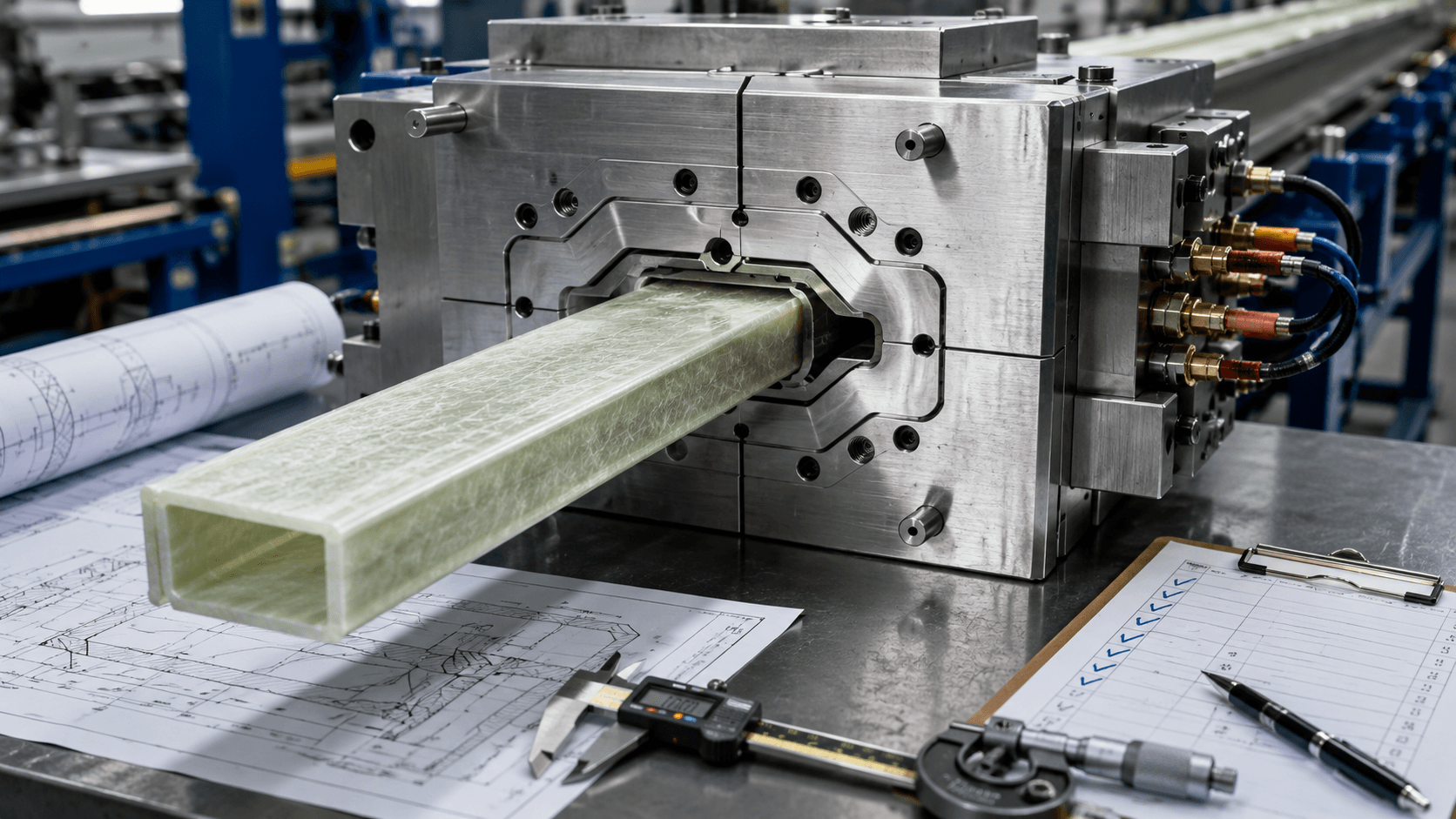
pultrusion die manufacturing
First Clarify What Is Being Manufactured
A pultrusion die is the forming and curing tool through which resin-impregnated reinforcement is continuously pulled. It is different from a fiberglass composite mold used to laminate a boat, cover or other molded part. Commercial discussions may use die, mold and tooling interchangeably, but the controlled project documents need to identify the actual scope.
That scope may involve the forming die alone or a wider tooling system with preforming guides, mandrels, supports, heating interfaces and sensors. The RFQ and drawing set should state which items are included, who supplies each interface and which components are subject to final inspection.
A Stage-Gate Framework for Pultrusion Die Manufacturing
The following is a buyer-focused manufacturing and quality framework, not a statement of one supplier’s fixed factory process. Individual projects may combine, add or reorder stages.
A controlled pultrusion die manufacturing plan commonly connects design release, manufacturing planning, rough and finish machining, interface preparation, surface finishing, dimensional inspection, assembly review and trial acceptance. The exact sequence and hold points depend on the tool design and project requirements.
| Stage | Required input | Main quality risk | Evidence or release output |
|---|---|---|---|
| 1. Product definition | Controlled profile drawing, die concept, datums, critical characteristics and revision | Machining a geometry that does not express functional intent | Approved drawing or model, characteristic list and revision record |
| 2. Manufacturing planning | Tooling material and surface-system requirements, split strategy, access and interfaces | An operation sequence that blocks later access or disturbs critical relationships | Manufacturing plan with hold points and internal/external responsibility |
| 3. Rough and finish machining | Released geometry, stock condition, machining allowances and setup datums | Distortion, datum transfer error, inaccessible features or damaged edges | In-process measurements and completed critical geometry |
| 4. Interface formation | Mandrels, split faces, fasteners, heaters, sensors, supports and line interfaces | Misalignment, interference or incompatible assembly features | Interface and assembly check record |
| 5. Surface finishing or treatment | Functional surface definition and treatment specification | Undefined “mirror finish,” edge damage, nonuniform treatment or unverified repair | Surface condition record and specified measurement results |
| 6. Final inspection | Approved drawing, inspection plan, measurement methods and acceptance rules | Measurements without a common datum, unsuitable instruments or incomplete coverage | Signed dimensional and surface inspection record |
| 7. Tool assembly and review | Matched components, setup instructions and defined responsibility | Cavity mismatch, mandrel shift, joint discontinuity or undocumented adjustments | Assembly status and open-item list |
| 8. Trial and acceptance | Resin and reinforcement information, production conditions and acceptance criteria | Treating one acceptable sample as proof of a transferable process window | Trial record, profile inspection and disposition of deviations |
The value of this sequence is traceability. Each stage converts an approved input into a reviewable output before the next stage makes changes harder or more expensive to correct.
Release the Product Definition Before Machining
Machining cannot compensate for an incomplete definition of function. Before manufacturing starts, the project needs one controlled drawing or model revision that identifies the cavity, split construction, mandrels, assembly relationships and critical interfaces.
ASME Y14.5 establishes a common language for stating and interpreting dimensions, datums and geometric tolerances on drawings and digital product definitions.1 Applying any standard is a contractual choice, but the underlying lesson is universal: a tolerance without a datum, feature definition and measurement method can be interpreted differently by design, machining and inspection teams.
A critical die dimension becomes reviewable only when its feature, datum, measurement method and acceptance rule are defined together.
Create a critical-characteristic list before release. For each characteristic, record:
- the drawing or model feature;
- the functional reason it matters;
- its datum or reference relationship;
- the planned manufacturing hold point;
- the inspection method;
- the acceptance rule and responsible reviewer.
Profile geometry, material path, entry design, mandrels and cavity relationships belong to the separate design task. See Pultrusion Die Design: Geometry, Materials & Surface Finish before freezing the manufacturing definition.
Plan Machining Around Datums, Access and Stability
A generic die-manufacturing plan often separates stock preparation, rough machining, stabilization where applicable, finish machining, surface work and final inspection. That is a planning framework rather than a universal recipe. The actual sequence depends on the selected substrate, die size, split arrangement, cavity geometry, available access, thermal interfaces and surface system.
Typical Manufacturing Operations and Their Purpose
The operations below describe a general buyer-review framework. They do not represent a fixed Unicomposite process, and not every operation applies to every tool.
| Typical operation | Primary purpose | What should be verified before moving forward |
|---|---|---|
| Stock preparation | Establish suitable starting material and initial manufacturing references | Material identity, initial condition and sufficient stock for the released manufacturing plan |
| Rough machining | Remove bulk material and establish preliminary geometry | Remaining stock, datum strategy, access for later operations and distortion risk |
| Stabilization, where required | Reduce the risk of dimensional movement before critical finishing operations | Applicable procedure, completion record and condition before finish machining |
| Finish machining | Produce functional cavities, interfaces and other critical geometry | Dimensions, datum relationships, transitions, edges and still-accessible features |
| Polishing or lapping | Develop the specified working-surface condition without losing functional geometry | Surface continuity, local edge condition, measurement method and dimensional effect |
| Coating or surface treatment, where specified | Apply the project-defined surface system | Surface preparation, coverage, interface condition and required supplier documentation |
| Final inspection | Verify conformity to the released definition before assembly or trial | Correct drawing revision, agreed datums, measurement records and disposition of deviations |
This operation list should not be converted into a fixed sequence by default. For example, a surface treatment, repair or assembly step may introduce an additional inspection hold point when it could affect a previously accepted characteristic.
The manufacturing review should answer four practical questions:
- Which features establish the manufacturing datums? Later setups and inspection need to reproduce the same functional references.
- Which features become inaccessible after assembly or surface treatment? Inspect them before access is lost.
- Which operations can change previously finished geometry? Thermal processing, coating, polishing, joining or rework may require an inspection hold point before and after the operation.
- Which relationships matter more than isolated sizes? Split-face alignment, mandrel position, cavity continuity and heater or sensor locations may depend on a common coordinate system.
Do not approve a process plan only because it lists machine names. Equipment matters only when it is connected to the geometry, material, setup, measurement and acceptance requirements of the actual tool.
Treat the Cavity, Split Faces and Mandrels as One System
The forming cavity cannot be inspected in isolation when the tool uses multiple sections or internal tooling. A split die may meet individual part dimensions and still produce an unacceptable assembled condition if the joint, alignment or clamping relationship shifts the functional cavity.
Inspection planning can therefore include, where relevant:
- split-face condition and joint continuity;
- cavity profile relative to assembly datums;
- mandrel geometry, support and alignment;
- entry and transition continuity;
- fastener, locating and support interfaces;
- heater and sensor locations relative to the controlled design;
- accessibility for assembly, cleaning and later maintenance.
Record both the free-state component measurements and the agreed assembled condition when assembly can affect the result. The report should also state any fixtures, supports or clamping conditions used during measurement so that the result can be reproduced.
Specify Surface Texture Instead of Asking for a “Mirror Finish”
“Mirror finish” is a visual description, not a complete engineering requirement. ASME B46.1 distinguishes roughness, waviness and lay and defines parameters for specifying surface texture.2 A functional surface requirement needs the selected parameter, evaluation conditions, measurement location and acceptance rule.
Surface quality matters because the die–material interface contributes to compaction, viscous resistance and friction during pultrusion. Peer-reviewed research shows that pulling force is influenced by interacting factors that include die geometry, die-surface condition, temperature, pulling speed, resin behavior and reinforcement configuration.3 A smoother measured surface may reduce one source of resistance, but it does not by itself guarantee stable pull force or an acceptable profile.
For a surface review, distinguish among:
- substrate condition;
- machined geometry;
- polishing or lapping;
- coating or other surface treatment;
- local edge and transition condition;
- the final inspection method.
Do not copy a roughness value, coating thickness or hardness from another die without confirming its function, substrate, reinforcement, resin exposure, repair approach and measurement method. If the project does not require a numeric surface parameter, define the visual and functional acceptance method explicitly rather than implying unmeasured precision.
Build the Inspection Plan Before Final Inspection
Final inspection should execute a previously agreed plan, not decide what matters after manufacturing is complete. ISO 10012:2026 describes a measurement-management approach intended to make measurement processes and equipment fit for purpose and capable of supporting reliable results.4 NIST likewise emphasizes calibration paths and traceable dimensional measurement as part of manufacturing quality.5
For each reported characteristic, the inspection record should identify:
- drawing or model revision;
- characteristic and nominal requirement;
- datum and measurement location;
- method, fixture and environmental condition when relevant;
- measuring-equipment identification and calibration status;
- actual result;
- acceptance, rejection or approved deviation;
- inspector and approval date.
Surface measurements need additional context. NIST’s surface-roughness work shows that reported parameters depend on instrument configuration, filtering, probe characteristics and measurement uncertainty.6 Reporting only an Ra number without the agreed method and measurement location can create false confidence.
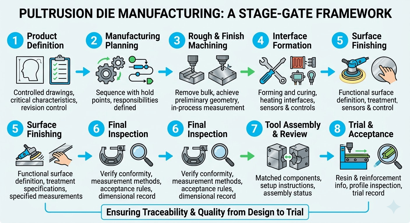
pultrusion die manufacturing a stage gate framework
Inspect the Tool and the Trial Profile for Different Reasons
Tool inspection verifies whether the die conforms to its released definition. A trial profile tests the interaction among tooling, resin, reinforcement, preforming, heating, line speed and pulling conditions. One cannot replace the other.
ASTM D3917 defines dimensional tolerance categories for standard thermosetting glass-reinforced pultruded shapes and notes that custom products can carry application-specific tolerances.7 The standard applies to pultruded products, not directly to die-manufacturing tolerances. A buyer can use the finished-profile requirement to help define functional tool characteristics, but the die drawing and trial-acceptance plan must state the project-specific relationship.
When cure evidence is part of trial acceptance, use the actual resin system and an approved method. ASTM D5028 covers differential-scanning-calorimetry evaluation of curing properties for applicable pultrusion resin solutions and can support research or specification acceptance.8 It does not provide a universal die temperature or production speed.
For the separate thermal-development method, see Pultrusion Die Heating: How Temperature and Line Speed Work Together.
Use Symptoms to Choose the Next Verification
An observed production problem is evidence that the tooling–process system needs investigation; it is not automatic proof that the die was manufactured incorrectly.
| Observed signal | Tooling evidence to review | Competing process evidence | Useful next comparison |
|---|---|---|---|
| Repeating longitudinal scratch | Map the profile mark to the cavity; inspect local surface and transition condition | Contamination, reinforcement contact or buildup | Compare the same mapped location before and after a controlled cleaning or inspection action |
| Wall-thickness or geometry drift | Cavity and mandrel measurements from agreed datums; assembly condition | Temperature, cure, reinforcement distribution and pulling setup | Compare tool results with profile measurements under a recorded baseline |
| Pulling force rises or oscillates | Entry, cavity surface, alignment, buildup and assembly interfaces | Resin state, reinforcement feed, temperature, speed and puller behavior | Synchronize force, temperature, speed and observation records before changing the tool |
| Mark or mismatch near a split line | Split faces, locating features and assembled cavity continuity | Uneven loading, contamination or setup | Measure the relevant components and assembled condition using the same references |
| Trial profile is acceptable at one setting but unstable later | Tool temperature/sensor interfaces and repeatable setup condition | Start-up state, material batch, cure window and line changes | Reproduce the accepted baseline and change one supported factor at a time |
This matrix is an investigation order, not a root-cause guarantee. Pultrusion modeling literature treats resin flow, heat transfer, cure, pulling force and stress as interacting parts of one system.9
What Should Be Included in a Pultrusion Die Acceptance Package?
A pultrusion die acceptance package should connect the approved tooling definition to inspection evidence, assembly status, authorized deviations and trial results where trial work is included. The required deliverables depend on the contract, but a buyer can request an acceptance package organized around the following items:
- Approved tooling drawing or model revision.
- Defined tooling scope and responsibility matrix.
- Material and surface-system identification at the agreed disclosure level.
- Critical-characteristic and inspection plan.
- Dimensional results with datums and methods.
- Surface-condition or surface-texture results where specified.
- Assembly and interface check record.
- Approved deviations and change history.
- Trial conditions and trial-profile results when trial work is included.
- Handling, cleaning and storage information appropriate to the supplied scope.
For post-delivery care, see Maintenance of Fiberglass Pultrusion Mold. Maintenance records should remain separate from the original manufacturing inspection record so later wear or repair is not confused with the as-delivered condition.
Pultrusion Die Manufacturing RFQ Checklist
Provide these inputs before asking a supplier to define manufacturing and inspection scope:
- controlled profile drawing and revision;
- critical dimensions, datums and functional interfaces;
- resin family and available cure information;
- reinforcement types and planned architecture;
- hollow features and mandrel requirements;
- intended production conditions and line interfaces;
- required tooling scope, including preforming components where applicable;
- substrate and surface-system requirements, if already approved;
- heating, sensor and controller interface requirements;
- required inspection characteristics and reporting format;
- trial-profile sampling and acceptance criteria;
- approved standards and editions;
- packaging, preservation and handling requirements;
- responsibility for design changes, deviations and final approval.
Do not leave an undefined item to be silently filled with a supplier’s standard practice. Record it as an open project question, identify who owns the decision and close it before the affected manufacturing stage.
Discuss Your Pultrusion Tooling Inputs
Explore our pultrusion molds and tooling page, or send us your profile drawing, critical tolerances, resin information, reinforcement plan, target production conditions and acceptance requirements for a project discussion. The applicable tooling scope, technical inputs, inspection requirements, trial responsibilities and commercial terms can then be documented during project review and quotation.
References
- ASME. “Y14.5—Dimensioning and Tolerancing,” 2018 edition, reaffirmed 2024. https://www.asme.org/codes-standards/find-codes-standards/y14-5-dimensiones-y-tolerancias
- ASME. “B46.1—Surface Texture (Surface Roughness, Waviness, and Lay),” 2019 edition, reaffirmed 2026. https://www.asme.org/codes-standards/find-codes-standards/b46-1-surface-texture
- Mukherji, A., and Njuguna, J. “An Assessment on Effect of Process Parameters on Pull Force During Pultrusion.” The International Journal of Advanced Manufacturing Technology 121 (2022): 3419–3439. https://doi.org/10.1007/s00170-022-09221-0
- International Organization for Standardization. “ISO 10012:2026—Quality Management—Requirements for Measurement Management Systems.” https://www.iso.org/standard/10012
- National Institute of Standards and Technology. “Dimensional Measurement Services.” Updated 2025. https://www.nist.gov/programs-projects/dimensional-measurement-services
- Vorburger, T. V., Renegar, T. B., Zheng, A. X., Song, J.-F., Soons, J. A., and Silver, R. M. “NIST Surface Roughness and Step Height Calibrations: Measurement Conditions and Sources of Uncertainty.” NIST, 2014. https://www.nist.gov/publications/nist-surface-roughness-and-step-height-calibrations-measurement-conditions-and-sources
- ASTM International. “ASTM D3917-23—Standard Specification for Dimensional Tolerance of Thermosetting Glass-Reinforced Plastic Pultruded Shapes.” https://store.astm.org/standards/d3917
- ASTM International. “ASTM D5028-25—Standard Test Method for Curing Properties of Pultrusion Resins by Thermal Analysis.” https://store.astm.org/d5028-25.html
- Safonov, A. A., Carlone, P., and Akhatov, I. “Mathematical Simulation of Pultrusion Processes: A Review.” Composite Structures 184 (2018): 153–177. https://doi.org/10.1016/j.compstruct.2017.09.093


