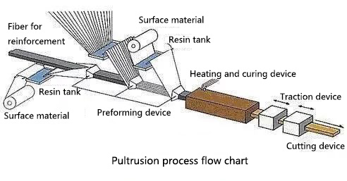
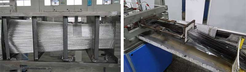
Pultrusion is a continuous manufacturing process for producing fiber-reinforced polymer profiles with a substantially constant cross-section. In conventional thermoset pultrusion, continuous reinforcement is pulled through resin impregnation and preforming stages, enters a heated die where the matrix cures and the profile takes its final shape, and then moves through a pulling and cutoff system.[4]
The word itself helps explain the method: pultrusion advances material by pulling it through the forming system. This distinguishes it from extrusion, in which material is pushed through a die. The process is well suited to rods, tubes, channels, angles, structural sections and other profiles whose cross-section remains consistent along their length.

pultrusion process
The Pultrusion Process at a Glance
Although line layouts and the integration of individual stages vary, a conventional thermoset pultrusion process can be understood through the following functional stages. Fraunhofer IGCV describes the core route as fiber impregnation, passage through a heated die, continuous haul-off and downstream finishing; it also distinguishes open-bath impregnation from injection and impregnation chambers.[1]
| Stage | Main function | What the next stage needs |
|---|---|---|
| Reinforcement supply | Feeds rovings, mats, fabrics or veils from creels or rolls | Stable paths and controlled delivery |
| Guidance and preforming | Organizes reinforcement and moves it toward the required cross-section | Correct placement without damaging or displacing fibers |
| Resin impregnation | Introduces the matrix into the reinforcement package | Adequate wet-out and manageable resin carryover |
| Final preforming and die entry | Consolidates the wet reinforcement before the forming die | A repeatable bundle shape and smooth entry |
| Heated die forming and cure | Defines the cross-section while the resin reacts and develops sufficient integrity | A profile that can exit without distortion or surface damage |
| Pulling | Provides the continuous force that advances the material | Stable motion coordinated with cure and downstream handling |
| Cutoff and inspection | Cuts the profile to length and checks release criteria | Identified, traceable and acceptable output |
This sequence is simple to visualize, but the stages do not operate independently. Reinforcement arrangement changes resin flow; resin behavior changes pressure and cure; heat transfer and reaction affect pulling force; and line speed changes the time available inside the heated die. A major review of pultrusion simulation therefore treats impregnation, resin flow and pressure, heat transfer, cure, pulling force and stress development as a coupled system rather than isolated settings.[2]
Step 1: Supply and Guide the Reinforcement
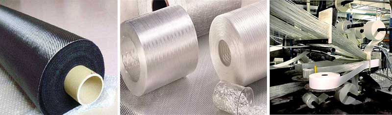
The process begins with continuous reinforcement drawn from creels and roll stands. Depending on the profile and its performance requirements, the reinforcement package may include longitudinal rovings together with mats, stitched fabrics or surface veils.
At this stage, the practical objective is not merely to feed enough fiber. Each reinforcement must arrive at the intended location without tangling, excessive rubbing or uncontrolled movement. Poor guidance can carry forward into local fiber shortage, resin-rich areas, wrinkling or an unstable bundle at the die entrance.
Material selection and reinforcement architecture deserve their own engineering review. For a focused explanation of glass-fiber forms, resin families and application inputs, see our guide to fiberglass reinforcement and resin materials for pultrusion.
Step 2: Preform the Reinforcement Package
Guides and preformers progressively arrange the reinforcement into a shape that can enter the impregnation and die system. For a simple solid profile, the path may be relatively direct. Hollow sections, thin walls, corners and local reinforcement features require closer control of fiber position and compaction.
Preforming has three related jobs:
- place the reinforcement where the cross-section needs it;
- reduce abrupt movement before die entry; and
- create a repeatable incoming package for impregnation and forming.
The preformer does not determine final dimensions by itself. It prepares the material for the die while preserving the intended reinforcement distribution.
Step 3: Impregnate the Fibers with Resin
In an open-bath arrangement, the reinforcement passes through a resin bath before final preforming and die entry. In injection pultrusion, resin is introduced in a closed impregnation chamber connected to the die system. Fraunhofer IGCV identifies both as established process variants and highlights resin flow through the fiber package as a central engineering concern.[1]
Neither method removes the need to control the incoming materials and process conditions. The objective is a reinforcement package with sufficient and consistent wet-out, without uncontrolled resin accumulation or trapped air. The appropriate arrangement depends on the resin system, reinforcement permeability, cross-section, line design and process objectives.
This is why a universal bath layout, injection pressure or resin viscosity cannot be selected from a generic article. Those values belong to a validated process window for a defined material and profile.
Step 4: Enter the Heated Die, Form the Profile and Cure the Matrix
The wet reinforcement enters the die, which establishes the profile geometry while heat initiates and advances the resin reaction. The goal is not simply to reach a high temperature. Heat must move through the tool and the developing composite in a way that gives the resin enough conversion and the profile enough integrity before exit.
Die geometry, heated length, zone arrangement, resin kinetics, reinforcement content, section thickness and line speed all influence the result. Research reviews describe heat transfer and cure as tightly linked to pulling force, residual stress and process stability.[2][3]
For that reason, temperature and speed should be treated as a verified combination rather than two independent target numbers. A process window is more useful than a copied “typical setting”: it connects material condition, zone response, line speed, pulling-force behavior and acceptance results for one defined profile.
For a focused method for developing and verifying that relationship, see how pultrusion die heating, cure and line speed work together.
The forming and curing stage is also where the tooling and the process meet. If a project requires a new die, the drawing, critical tolerances, reinforcement plan, resin information, target output and acceptance criteria should be aligned before tooling details are finalized.
Step 5: Pull the Profile Continuously
The pulling unit advances the profile and every upstream material through the line. Reciprocating grippers or caterpillar-style pullers are common arrangements, but the equipment configuration is a separate purchasing and line-design question. See our overview of pultrusion machine and line equipment for that scope.
Pulling force is more than a machine-capacity value. A stable baseline can help operators recognize changes in friction, cure behavior, material delivery or die condition. A rising or oscillating trend is a signal to investigate the process; it is not, by itself, proof of a single root cause.
Before changing a setting, record the profile, material lots, line speed, temperature response, pulling-force trend and observed defect location. Change one supported factor at a time, then compare the output with the last accepted baseline.
Step 6: Cut, Finish and Inspect the Profile
After the profile exits the pulling system, a traveling or synchronized saw cuts it to the specified length. Drilling, machining, marking, cleaning or packaging may follow when required by the finished-part specification.
Inspection should reflect the drawing and the intended use. Common categories include:
- cross-section dimensions, length, straightness, bow and twist;
- surface condition and visible discontinuities;
- cut quality and secondary-operation features;
- material and production-lot traceability; and
- mechanical, thermal, electrical or other tests required by the acceptance plan.
Not every characteristic needs the same sampling frequency, and no single test proves overall quality. The inspection plan should identify critical characteristics, measurement methods, sampling rules, acceptance criteria and the records retained for release.

the continuous manufacturing process for composite profiles
What Controls Pultrusion Process Stability?
A stable pultrusion line depends on relationships, not isolated numbers. Five control groups are especially useful when reviewing the process:
Reinforcement delivery
Check paths, tension behavior, splice events and the position of rovings, mats and veils. A material that enters the line inconsistently cannot be corrected completely by changing die temperature.
Impregnation and resin condition
Track the factors that affect wet-out and flow for the selected resin system. A change in material temperature, formulation, storage condition or reinforcement permeability can alter the response even when the machine settings have not changed.
Die entry and forming
Observe buildup, fiber displacement, entry friction and the location where a surface or dimensional symptom first appears. The physical location of a symptom can narrow the investigation more effectively than a general list of possible defects.
Heat, cure and line speed
Compare zone response, line speed, pulling force and finished-profile condition as one record. A temperature reading alone does not show the complete thermal history inside a thick or complex section.
Tooling and downstream handling
Separate die-related symptoms from pulling, cutoff, support and handling effects. A scratch that appears after the die exit should not automatically be diagnosed as cavity damage.
A Practical Process-Review Sequence
When output begins to drift, use a controlled investigation rather than changing several settings at once:
- Define the exact symptom and the first location where it can be observed.
- Stop or secure the line according to the facility’s safety procedures before inspection or access.
- Preserve the last accepted baseline and record current material lots and process trends.
- Check reinforcement delivery, impregnation, die entry, heat response, pulling and downstream contact points.
- Rank plausible causes using the observed location and recent changes.
- Test one supported adjustment under controlled conditions.
- Verify dimensions, surface condition and any required performance criteria before release.
- Document the accepted condition or escalate the issue for tooling, material or process review.
This sequence prevents a common mistake: treating every defect as a die problem. Material delivery, resin behavior, thermal response, pulling and downstream equipment can produce similar visible symptoms.
Where Pultrusion Fits—and Where It Does Not
Pultrusion is fundamentally suited to continuous profiles with a constant cross-section. It can combine longitudinal reinforcement with other fiber forms to tailor the laminate, but the process does not turn a continuously changing three-dimensional part into a natural pultrusion candidate.
Designers should evaluate another molding or fabrication route when the part requires substantial changes in cross-section, deep three-dimensional features, or quantities for which dedicated tooling may not be economically justified after expected production volume, part value, downstream operations and alternative processes are compared. Secondary cutting, drilling, bonding or assembly can add features, but those operations should be considered in the part and acceptance plan.
For a fuller decision framework, including directional properties, tooling economics and geometry limits, read the advantages and disadvantages of the FRP pultrusion process.
Information Needed to Define a Pultrusion Process
Before a process or tooling discussion, prepare:
- the profile drawing and revision;
- critical dimensions and tolerances;
- reinforcement and resin information, if already specified;
- service environment and applicable performance requirements;
- required cut length and downstream operations;
- expected output or order quantity;
- inspection methods, sampling and acceptance criteria; and
- any existing trial records, defect photos or accepted baseline data.
These inputs allow the line, material, tooling and inspection requirements to be reviewed as one system instead of a collection of generic settings.
Frequently Asked Questions
Is pultrusion the same as extrusion?
No. Pultrusion pulls continuous reinforcement and resin through a forming and curing system. Extrusion generally pushes a material through a die. Both can produce continuous profiles, but their materials and process mechanics are different.
Does every pultrusion line use an open resin bath?
No. Open-bath impregnation is common, while closed injection and impregnation chambers are also used. The appropriate route depends on the material system, reinforcement package, profile and process objectives.[1]
What is the most important pultrusion process setting?
There is no single universal setting. Reinforcement delivery, impregnation, die geometry, heat transfer, resin cure, line speed and pulling force interact. The useful output is a validated process window and acceptance record for a defined profile—not an isolated temperature or speed copied from another line.[2]
If Your Pultrusion Project Requires New Tooling
If your project requires a new die or a review of an existing tooling concept, visit our pultrusion molds and tooling page, then send us the cross-section drawing, critical tolerances, resin information, reinforcement plan, target output and acceptance requirements. We will use those inputs to define the tooling discussion scope and identify the product or document requirements that still need confirmation.
References
- Fraunhofer Institute for Casting, Composite and Processing Technology IGCV, “Pultrusion.” Process description and open-bath versus injection/impregnation variants.
- Safonov, A. A., Carlone, P., and Akhatov, I., “Mathematical Simulation of Pultrusion Processes: A Review,” Composite Structures, 184 (2018), 153–177.
- Vedernikov, A., Safonov, A., Tucci, F., Carlone, P., and Akhatov, I., “Pultruded Materials and Structures: A Review,” Journal of Composite Materials, 54(26) (2020), 4081–4117.
- American Composites Manufacturers Association, “Guidelines and Recommended Practices for Fiber-Reinforced-Polymer Architectural Products,” Appendix E, Pultrusion.
info@unicomposite.com