 info@unicomposite.com


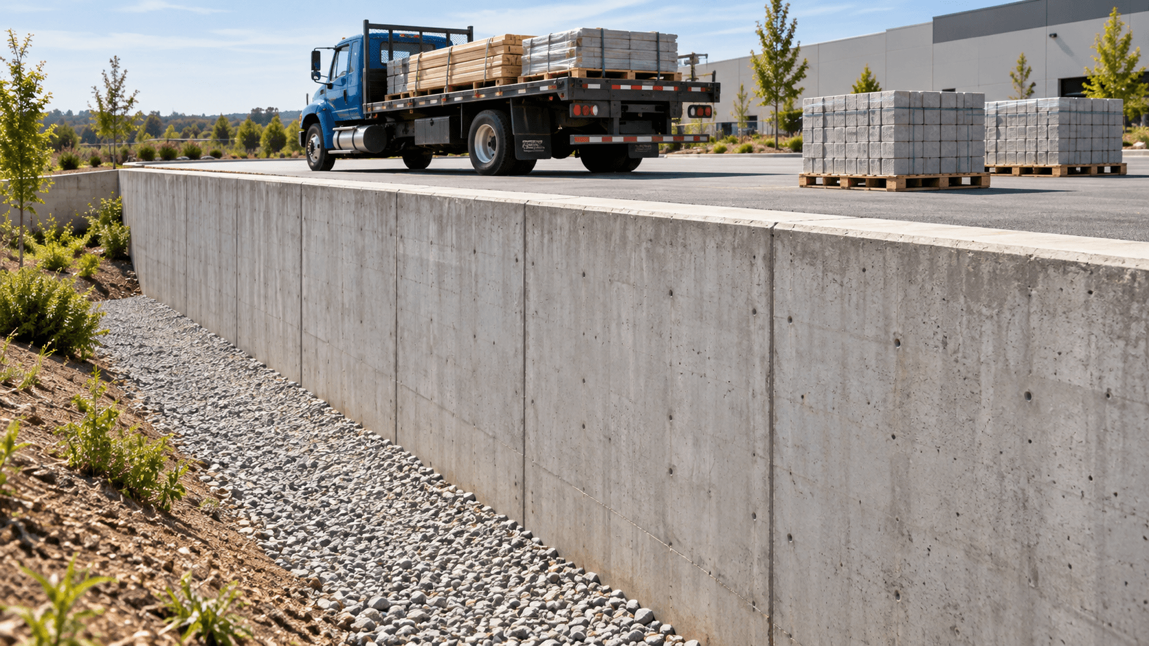
A retaining wall surcharge is an additional load on the ground behind a wall that increases lateral pressure beyond the pressure from the retained soil’s own weight. Traffic, nearby foundations, construction equipment, and stored materials can all create surcharge loading. The resulting pressure depends on the load’s footprint and location, the soil, and the wall’s movement and restraint—not simply on the weight placed nearby. [1][2]
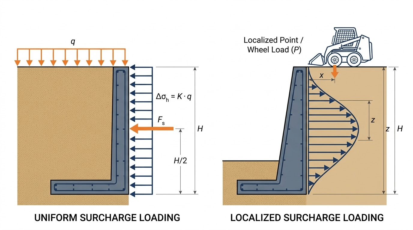
For a suitably idealized uniform surcharge, the additional lateral pressure can be calculated as Δσh = Kq. A wheel, crane outrigger, narrow footing, or finite loading strip may need a different pressure distribution. Choosing the load model comes before choosing a coefficient or calculating a wall member. [1]
retaining wall surcharge
Identify the load before assigning a pressure
Start with what applies the load and where it acts. A loaded storage area, a vehicle wheel, and a building foundation can impose very different stress patterns even when their total vertical forces are similar.
FHWA distinguishes distributed surcharge from point, line, and strip loads. Its examples include traffic, buildings, construction equipment, and stockpiles. Caltrans similarly requires the surroundings and construction methods to be considered when evaluating loads on its shoring systems. Temporary use matters: equipment or materials present during construction can create a loading case absent from the finished site. [1][2]
| Loading idealization | Quantity to define | Why the footprint matters |
|---|---|---|
| Broad, uniform surface loading | Applied pressure, such as lb/ft² (psf) or kPa, and the loaded area | A uniform lateral increment is an idealization that needs an appropriate loading extent. |
| Strip loading | Surface pressure, strip width, distance from the wall, orientation, and length along the wall | A finite-width road or storage strip need not produce constant lateral pressure with depth. |
| Line loading | Force per unit length, such as lb/ft or kN/m, location, orientation, and actual loaded length | A narrow continuous footing may be represented differently from a broad surface pressure. |
| Point or localized loading | Force, such as lb or kN, its location, and the actual contact footprint | A wheel or outrigger is localized; the point representation is a calculation model, not a description of its physical contact area. |
The table identifies models, not a rule assigning every vehicle or footing to one category. Record the actual dimensions and load positions before selecting an idealization. For a strip, distinguish the near and far edges and record its orientation and actual length along the wall. Check whether the selected strip or line-load model assumes loading parallel to the wall and an idealized extent. For a localized load, include its position along the wall as well as its distance behind it. These geometric variables appear in the localized-load arrangements described by FHWA and Caltrans. [1][2]
Water pressure needs a separate entry. Caltrans explicitly distinguishes groundwater pressure from surcharge loading. Do not put water pressure into a surface-load allowance and assume it has been addressed. For that related task, see our retaining wall drainage and backfill guide. [2]
Match the earth-pressure condition to wall movement
The coefficient K is not a material rating for the wall. It represents the earth-pressure condition assumed in the analysis.
An active condition develops as a wall moves away from the retained ground sufficiently to mobilize it. A no-lateral-movement idealization uses at-rest pressure. FHWA explains the relationship between movement and pressure, while Caltrans makes the same distinction in its shoring guidance. Supports, foundations, surrounding structures, and movement limits therefore affect the choice of model. [1][3]
For a simple active-pressure case with a vertical, frictionless wall, level homogeneous cohesionless backfill, and no groundwater, the familiar Rankine coefficient is:
Ka = (1 − sin φ′) / (1 + sin φ′)
Here, φ′ is the soil’s effective friction angle. Those assumptions matter: a sloping surface, wall friction, different soil conditions, or restricted movement can make this simplified expression inappropriate. A component described as “flexible” does not by itself establish that the complete wall can develop the assumed active condition. [1]
Calculate the uniform surcharge increment
Uniform pressure within a finite loaded area does not automatically justify a constant lateral increment over the analyzed height. Confirm the loaded extent and its position relative to the wall before using the broad uniform-surcharge idealization. [1][2]
For the uniform-loading idealization, FHWA gives the additional lateral pressure as the applied surface surcharge multiplied by an appropriate earth-pressure coefficient. Caltrans distinguishes the active and at-rest coefficients in its corresponding uniform-load expression. [1][2]
Δσh = Kq
- q is the uniform vertical surface pressure.
- K is the coefficient appropriate to the assumed condition.
- Δσh is the additional horizontal pressure; it has the same pressure units as q.
- H is the vertical height of the assumed surcharge-pressure diagram between its stated top and bottom levels.
If that increment is constant over the defined height H, integrating the rectangular pressure diagram gives:
Fs = KqH
Ms = KqH² / 2
Fs is the surcharge-induced horizontal force per unit length of wall. Ms is its moment about the base of the assumed pressure diagram, also per unit wall length. The resultant acts at H/2 above that base. Internal bending moments and support reactions require analysis of the actual wall system. In the example below, the force and moment are reported per foot of wall length; they are not the total values for an entire wall or a discrete post. These are consequences of the rectangular diagram; they are not formulas for every surcharge or for total wall demand.
Worked example: surcharge only, with stated assumptions
Assume a broad uniform surcharge q = 200 psf over the relevant retained ground and an analyzed height H = 6 ft. For the active case, assume φ′ = 30°, the simplified geometry and soil conditions above, and sufficient movement to develop active pressure. These are hypothetical teaching inputs, not recommended site loads or Unicomposite product limits.
The active coefficient is Ka = (1 − 0.5)/(1 + 0.5) = 1/3. The comparison column below uses an assumed K = 0.50 only to show coefficient sensitivity; it does not establish the correct at-rest coefficient for a particular site.
| Unfactored surcharge increment only; q = 200 psf, H = 6 ft | Active example, K = 1/3 | Comparison with assumed K = 0.50 |
|---|---|---|
| Additional horizontal pressure, Kq | 66.7 psf | 100 psf |
| Horizontal force per unit wall length, KqH | 400 lb/ft | 600 lb/ft |
| Moment per unit wall length about the diagram base, KqH²/2 | 1,200 lb-ft/ft | 1,800 lb-ft/ft |
| Resultant height above that base | 3 ft | 3 ft |
For example, the active-case force is (1/3) × 200 × 6 = 400 lb/ft. Multiplying by the resultant height gives 400 × 3 = 1,200 lb-ft/ft. The pressure is rounded to one decimal place for display; the force and moment use the unrounded coefficient.
The comparison shows why the pressure condition matters even when the surface load is unchanged. It does not mean that changing K changes a wall’s capacity by the same proportion. Soil self-weight pressure, water pressure, other load cases, applicable factors, structural resistance, and stability checks are outside this surcharge-only calculation. A real design must address them separately.
Use a different distribution for localized loads
The rectangular diagram above is not a universal substitute for a wheel, footing, or stockpile near a wall. FHWA explains that point, line, and strip loads act over limited areas and generally produce additional lateral pressure that varies with depth; elasticity-based methods are commonly used to evaluate that distribution. [1]
A localized-load analysis needs more than a single total weight. It needs the footprint, load intensity or force, distance to the loaded area, position along the wall, and a model suited to the wall and soil conditions. Caltrans’ separate strip, line, and point-load arrangements illustrate why those inputs cannot be silently replaced with one broad surcharge pressure. [2]
This also explains a common comparison error: psf is pressure, lb/ft is line load, and lb is force. The quantities cannot be inserted interchangeably into the same formula. Dividing a vehicle’s weight by an arbitrary ground area does not establish a valid uniform-surcharge model.
Do not infer a universal safe setback from a fixed fraction of wall height or a sketch of an influence line. The calculation must use the actual load location and the applicable model. A distance that appears in one method or loading case is not automatically a clearance rule for every wall.
retaining wall surcharge
Keep the pressure model separate from wall capacity
Calculating the surcharge increment establishes one part of the demand. It does not verify the wall’s resistance or serviceability.
For an FRP option, the resulting demand must be coordinated with the proposed structural arrangement, members, connections, supports, and product-specific design evidence. A fiberglass material name or a member datasheet alone cannot establish an allowable surcharge for a complete wall. Our FRP retaining wall materials guide explains that distinction between material selection and a wall system.
The useful outcome of surcharge assessment is a traceable loading case: what applies the load, how it is distributed, where it acts, which pressure condition is assumed, and what pressure diagram is passed into the wall design. Check construction-stage use as well as the permanent layout, and revisit the loading case if equipment, storage, or nearby structures change.
If you are considering FRP components, review our FRP Retaining Wall product page and send the proposed wall configuration, retained height, site location, and available soil and loading information. The responsible project designer must establish the applicable surcharge cases and verify the complete wall design.
References
- FHWA, Soils and Foundations Reference Manual, Volume II, FHWA-NHI-06-089, December 2006, Chapter 10: earth-pressure conditions and simplified coefficients, pp. 10-10–10-12; surcharge loading, §§10.4.1–10.4.3, pp. 10-29–10-31.
- Caltrans, Trenching and Shoring Manual, Chapter 5: Surcharges, July 2025, §§5-1, 5-1.02 and 5-1.03. Its project requirements concern the shoring work described in that manual.
- Caltrans, Trenching and Shoring Manual, Chapter 4: Earth Pressure Theory and Application, July 2025, §4-2.03, shoring movement and loading.


