 info@unicomposite.com


Retaining wall drainage starts by controlling where water enters the site, then providing a filtered route for water behind the wall to reach a suitable outlet. Backfill must support the wall’s design assumptions as well as the drainage arrangement. Gravel, a drainpipe, or a corrosion-resistant wall face alone does not establish that the system will remain drained. [1][3]
For contractors, engineers, and procurement teams, the useful question is whether the proposed water path works with the actual soil, wall configuration, and discharge conditions.
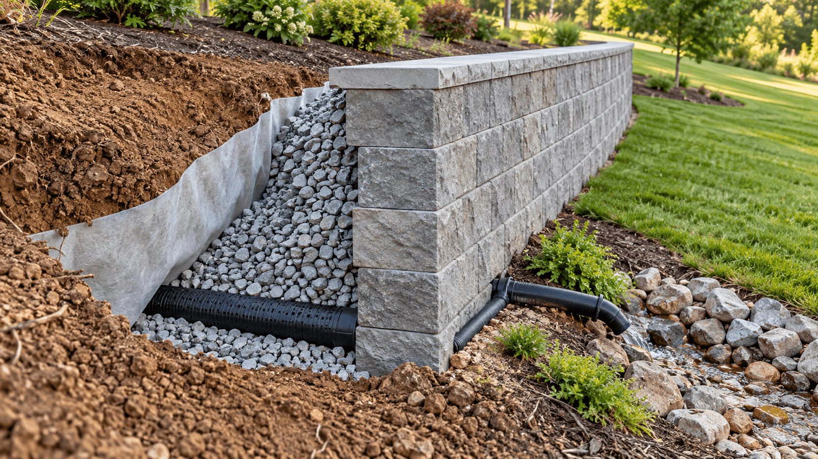
retaining wall drainage
Separate surface runoff from groundwater
Water can reach a retaining wall from rainfall flowing across the finished grade, roof drainage, irrigation, or seepage through the ground. Seasonal groundwater may reach the backfill or foundation even when the surface looks dry.
These sources need different responses. Surface grading and collection features manage runoff before it enters the retained soil. Subsurface drainage manages seepage and water that has infiltrated. A buried collector should not be assumed to replace the site’s surface-water plan. Allan Block’s water-management guidance for its segmental walls makes this distinction and identifies irrigation, downspouts, and seasonal groundwater as separate inputs. [2]
Caltrans’ January 2026 guidance for conventional concrete retaining walls also calls for surface drainage to be directed away from the wall and for additional groundwater measures where needed. If drainage cannot be relied upon, its guidance requires the wall to be designed for hydrostatic pressure. That is a design decision, not something resolved by adding a pipe to a drawing. [1]
Follow the entire drainage path
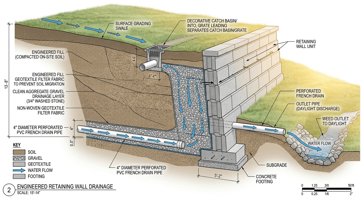
A drainage detail needs connected functions. The following table describes their roles; their locations and dimensions depend on the wall and site. FHWA illustrates several arrangements rather than one universal section. [3]
| Function | What it does | Coordination question |
|---|---|---|
| Water-entry control | Limits runoff entering retained soil | Where does surface water go? |
| Filter | Retains soil while allowing water across the interface | Is it compatible with the adjacent soil? |
| Drainage zone or drainage core | Provides a water path | Does it connect to the collector or outlet? |
| Collector and conveyance | Carries collected water onward | Are connections and elevations continuous? |
| Outlet | Discharges water from the system | Is the discharge destination usable and maintainable? |
Use the plan and section together to trace that route. A section may show a pipe behind the wall while leaving its destination unclear. Record the connection or outlet location on the plan as well. A missing connection is a gap in the drainage scheme even if each component has been specified.
Choose backfill for its particular zone
“Retaining wall backfill” can describe more than one material. A drainage zone, structural fill, and retained soil can have different functions and acceptance criteria.
For example, CMHA distinguishes the gravel fill immediately behind segmental wall units from the reinforced soil containing horizontal reinforcement and the retained soil farther behind. The drainage gravel’s role does not make it a substitute for every other zone. These are segmental-wall terms; another wall configuration needs its own defined zones. [4]
FHWA’s research on open-graded aggregates explains why material selection involves more than permeability. Such aggregates are used for both drainage and structural backfill, but their shear strength depends on factors including loading conditions, compaction, confinement, and particle characteristics. A stone size or commercial aggregate name does not by itself establish the strength assumed in a wall design. [5]
For procurement, keep the requirements for each zone separate: material gradation and cleanliness, required engineering properties, placement requirements, and the verification specified for the project. Reusing excavated soil should be assessed against those requirements rather than accepted solely because it is available. Caltrans includes the suitability of excavated soil among its retaining-wall investigation inputs. [1]
Match the filter to the soil and drainage material
A filter must allow water to pass while preventing damaging soil migration. FHWA identifies both granular filters and geotextiles as options. Where adjacent soils satisfy the relevant filtration criteria, a geotextile is not automatically required. Conversely, placing open-graded stone beside finer soil requires the interface to be assessed; calling the stone “free-draining” does not resolve filtration. [3]
CMHA likewise describes a geotextile between the gravel fill and adjacent soil as an option for protecting a segmental wall’s gravel zone from clogging. [4]
Specify the filtration requirement for the actual interface. A generic “landscape fabric” description is insufficient to establish compatibility. The drawing should identify which soil the filter retains and where water crosses it. This also prevents a separation detail from being mistaken for a verified drainage design.
Coordinate collectors, outlets, and groundwater conditions
The selected drainage medium must connect to its discharge route. FHWA describes both aggregate drainage zones and geocomposite drains, which combine a filter with a collection core. Connections and joints for geocomposites are product-specific. [3]
For its segmental-wall systems, Allan Block discusses outlets to daylight or an underground drainage system, as well as protecting outlets from crushing and plugging. Its pipe dimensions and spacings belong to that system’s guidance and should not be transferred to an FRP wall. [2]
A project detail should establish the receiving location, available elevations, and conditions that could obstruct discharge. A storm-drain connection needs coordination with the site drainage design; an outlet to the surface needs an appropriate discharge location. Confirm the applicable permissions and maintenance access before treating the route as complete.
Where groundwater cannot be kept out of the backfill, a face drain alone may be inadequate. Caltrans discusses measures at the wall, behind the backfill, and beneath it for conventional walls. The project team must select the arrangement that addresses the identified water source. [1]
retaining wall drainage 2
Check concealed work before backfilling hides it
Drainage performance depends on continuity that may become difficult to inspect later. Caltrans’ construction guidance calls for as-built records of concealed subsurface drains and checks of filter damage, material condition, and geocomposite connections. Its detailed installation requirements apply to the specified Caltrans work; the broader lesson is to document the completed path. [6]
Before covering the drainage work, use the approved project details to verify:
- The supplied filter, drainage material, and pipe match their designated locations.
- Filter damage and displaced connections have been addressed as specified.
- Collector and outlet locations and elevations have been recorded.
- Inspection or cleanout points remain accessible where provided in the design.
- Photographs show joints and transitions that will become concealed.
Keep these records with the wall’s maintenance information. A visible outlet is only one part of the route; future inspection also needs to know where the concealed collectors and connections are located.
Apply the same coordination to an FRP wall proposal
An FRP wall proposal still needs a site-specific water-management arrangement. The wall member’s material does not define the soil filter, collector route, or discharge destination. Coordinate any drainage opening with the actual wall detail; a generic sketch is not a reason to drill an unspecified opening in a structural member.
For the material and structural-role questions that come before selecting the wall components, see FRP retaining wall materials and tradeoffs.
Before finalizing a wall proposal, bring together the site water sources, defined backfill zones, filter criteria, connected drainage route, and project design assumptions. The result should be a coordinated plan and section, with material requirements and inspection records that refer to the same arrangement.
If you are considering FRP components, review our FRP Retaining Wall product page and send the proposed wall configuration, retained height, site location, and available soil and water information. Site drainage and structural design remain with the responsible project design team.
References
- Caltrans, Geotechnical Manual: Conventional Retaining Walls, January 2026, investigation requirements and “Surface and Subsurface Drainage Systems,” pp. 2 and 9.
- Allan Block, Tech Sheet 617: Proper Water Management, 2017, pp. 1–2. Guidance for Allan Block segmental retaining walls.
- FHWA, Soils and Foundations Reference Manual, Volume II, FHWA-NHI-06-089, December 2006, Chapter 10, pp. 10-47–10-50.
- CMHA, What Are the Basic Components of an SRW System?, sections on retained soil, gravel fill, and reinforced soil.
- FHWA, Strength Characterization of Open-Graded Aggregates for Structural Backfills, FHWA-HRT-15-034, Chapter 2, June 2015.
- Caltrans, Construction Manual, Section 4-68: Subsurface Drains, sections 4-6803 and 4-6803D.


