 info@unicomposite.com


Introduction
Corrosion costs the global economy an estimated $2.5 trillion every year — and a disproportionate share of that damage begins not with the longitudinal bars engineers specify on structural drawings, but with the stirrups. Rebar rings sit closer to the beam surface than any other embedded reinforcement, often with as little as 25–40 mm of concrete cover. That proximity means faster chloride penetration and an earlier onset of the rust-expansion cycle that eventually splits the beam from the inside out.
For engineers and procurement managers evaluating reinforcement options, the choice between conventional steel stirrups and fiberglass (GFRP) rebar rings is becoming a standard part of specification reviews for infrastructure exposed to moisture, chemicals, or electrical fields. This article delivers a direct, property-by-property comparison to help you determine which material performs better for your specific beam application — including an honest look at where each material falls short.
Unicomposite is an ISO-certified pultrusion manufacturer producing FRP profiles and custom composite components for civil infrastructure, power utilities, wastewater treatment, and agricultural construction. The manufacturing observations throughout this article draw on that production and application experience.

fiberglass vs steel rebar rings stirrups in concrete beams
1. Understanding Rebar Rings (Stirrups) and Their Role in a Concrete Beam
1.1 What Stirrups Actually Do Structurally
Stirrups are not secondary reinforcement in any meaningful sense. In a loaded concrete beam, diagonal tension stresses develop at roughly 45° to the beam axis — and concrete, which handles compression well but fails in tension, cannot resist these forces alone. Stirrups intercept those diagonal cracks, transfer shear loads, and confine the concrete core to prevent sudden brittle failure.
Their geometry matters as much as their material. A closed rectangular or circular loop fully encases the beam cross-section, providing confinement pressure that increases ductility and ultimate load capacity. Specifying the wrong material at this component — even when longitudinal bars are correctly designed — can compromise the beam’s entire failure mode and long-term structural integrity.
1.2 Where Corrosion Attacks First — and Why
Steel stirrups consistently fail before longitudinal bars in corrosion-prone environments, and the geometry explains why. Structural codes permit thinner concrete cover over shear reinforcement than over primary tension steel. Chloride ions from seawater, deicing salts, or industrial runoff reach that depth far faster than the cover protecting the main bars.
In bridge deck inspections and marine structure surveys, stirrup corrosion is routinely the first and most severe failure mode identified. Rust products occupy roughly three to four times the volume of the original steel, generating expansive pressure that cracks the cover concrete, accelerates further ingress, and ultimately causes visible spalling. One recurring challenge in low-clearance beam designs — where formwork constraints force cover thicknesses to the minimum code-permissible limit — is that even epoxy-coated steel stirrups begin showing disbondment-driven corrosion within 15–20 years in tidal or splash-zone exposure. Catching this failure mode at the specification stage, rather than during a costly repair cycle, is where material selection delivers the most leverage.
2. Material Properties: Fiberglass vs Steel Rebar Rings
Beyond the corrosion mechanism, the full property profile of each material drives specification decisions across a range of beam applications. The table below compares the key mechanical and physical properties of conventional carbon steel and GFRP rebar rings:
| Property | Steel (Grade 60 / B500) | GFRP (E-glass / Vinyl Ester) |
|---|---|---|
| Tensile Strength — Longitudinal (MPa) | 420–500 | 550–750 (standard lay-up) |
| Elastic Modulus (GPa) | ~200 | 40–60 |
| Density (g/cm³) | 7.85 | 1.9–2.1 |
| Corrosion Resistance | Poor (requires cover and coatings) | Excellent — chemically inert |
| Thermal Conductivity (W/m·K) | ~50 | ~0.3–0.4 |
| Electromagnetic Neutrality | No — conductive | Yes — fully dielectric |
| Typical Design Service Life | 30–50 years (aggressive exposure) | 50+ years (per ACI 440.6) |
One clarification engineers should note: GFRP tensile strength figures are direction-dependent. The values above apply longitudinally — along the fiber axis — which is the relevant direction for a closed stirrup resisting tension at its corners and straight legs. Transverse strength is significantly lower, which is why bend zones in GFRP stirrups require a minimum bend radius and are not stress-rated equivalently to the straight sections. Any manufacturer data sheet should specify both values.
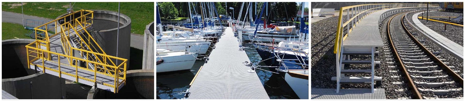
GFRP stirrups are approximately 75% lighter than equivalent steel sections. The density advantage matters during beam cage assembly — particularly in elevated formwork, confined-space installations, or long-span precast operations where handling ergonomics affect productivity and worker safety. More consequentially, eliminating the rust-expansion mechanism removes cover cracking from reinforcement corrosion as a long-term maintenance concern. For electrical infrastructure, the dielectric property of fiberglass rebar rings removes a design constraint that steel cannot address without expensive isolation measures.
The lower elastic modulus of GFRP is a genuine trade-off. GFRP stirrups deflect more under equivalent load before reaching their higher ultimate tensile capacity. Beam designs using GFRP shear reinforcement must satisfy serviceability limit state checks using the reduced modulus value — ACI 440.1R and CSA S806 both provide the relevant deflection and crack width calculation frameworks for practitioners working through this for the first time.
3. Performance in Aggressive Environments
3.1 Marine, Coastal, and Chemical Exposure
Steel corrodes through an electrochemical process: chloride ions penetrate the concrete matrix, break down the passive oxide layer on the rebar surface, and initiate oxidation that produces expansive iron oxides. No coating system or concrete mix design fully stops this process in permanently wet or splash-zone environments — it only slows it.
GFRP’s polymer matrix is chemically inert to chlorides, sulfates, and most industrial acids encountered in wastewater treatment and agricultural construction. ACI 440 explicitly recognizes GFRP reinforcement as a corrosion-immune option for aggressive exposure categories. Consider a concrete beam in a coastal wastewater treatment facility where formwork geometry limited cover to 30 mm over the stirrups — a scenario increasingly common in retrofit and upgrade projects on constrained sites. At that cover depth, uncoated steel stirrups face chloride threshold breach within a decade in a marine-adjacent environment. Specifying GFRP stirrups eliminates that constraint entirely, without requiring increased section depth or epoxy-coating premiums.
3.2 Electrical and EMI-Sensitive Applications
Steel rebar in a concrete beam conducts electricity and supports the formation of eddy currents in varying magnetic fields. For beams in power substation structures, transformer foundations, MRI facility construction, or communications tower bases, this is not a theoretical concern — it directly affects equipment performance and regulatory safety clearance requirements.
Fiberglass rebar rings are fully non-conductive. They introduce no inductive interference, support no galvanic pathways, and create no grounding complications in electrically sensitive structures. Specify GFRP stirrups in substation beam cages where steel reinforcement would require additional isolation engineering — the dielectric property of the material resolves the problem at the source rather than managing it downstream.

steel vs fiberglass stirrups
4. Structural and Installation Considerations
4.1 Bend Radius, Shape Fabrication, and Tolerances
Fabrication process determines what is possible — and what is not — with GFRP stirrups. Steel stirrups can be bent on-site to accommodate last-minute design changes or fit adjustments. GFRP, once pultruded and cured, cannot be field-bent without fracturing the fiber architecture at the bend zone.
At Unicomposite, closed rectangular stirrup geometries and circular rebar rings are formed during the pultrusion and filament-winding stage under controlled fiber orientation and resin cure conditions. Dimensional tolerances — loop width, corner radius, leg length — are set at manufacturing, not adjusted on-site. This means procurement coordination must begin from finalized beam drawings: stirrup geometry is specified and confirmed before fabrication, not after. For projects with stable design documentation, this presents no practical limitation. For fast-track or change-order-heavy projects, it requires tighter pre-fabrication alignment between the structural engineer and the FRP supplier.
Custom stirrup geometries — including non-rectangular loop profiles and variable-diameter rings for tapered beam sections — are available on a project basis. Engaging the manufacturer at the design stage, rather than the procurement stage, avoids late specification changes that affect lead time.
4.2 Bond Strength and Concrete Compatibility
Deformed steel rebar achieves mechanical bond through its ribbed surface profile, interlocking physically with the surrounding concrete matrix. GFRP stirrups achieve equivalent bond performance through sand-coated or helically wound surface treatments applied during manufacturing.
ACI 440.1R bond test data indicates that sand-coated GFRP bars develop bond strengths in the range of 10–18 MPa depending on embedment conditions and concrete compressive strength — performance adequate for shear reinforcement applications when development length provisions are satisfied. ASTM D7913 governs the bond characterization test method. Engineers should verify that the specific GFRP product being specified provides a manufacturer-supplied bond strength value, not just a generic material classification.
The table below summarizes the key installation and design parameters for engineers transitioning from steel to GFRP stirrups on a beam project:
| Parameter | Steel Stirrups | GFRP Stirrups |
|---|---|---|
| Field Bendability | Yes — standard practice | No — factory-formed only |
| Minimum Bend Radius | 3–4× bar diameter | 3–6× bar diameter (grade-dependent) |
| Surface Treatment | Deformed ribs | Sand-coated or helical fiber wrap |
| Tensile Strength at Bend Zone | Not reduced | Reduced — do not apply full bar rating |
| Bond Standard Reference | ASTM A615 / BS 4449 | ACI 440.1R / ASTM D7913 |
| Typical Available Diameters | 6–50 mm | 6–32 mm (custom sizes on request) |
5. Total Cost of Ownership: Upfront Price vs. Lifecycle Value
5.1 Initial Material Cost Differential
Procurement managers should expect GFRP stirrups to cost roughly 2–4 times more per kilogram than equivalent steel rebar — a range consistent with civil infrastructure procurement data from North American and European projects reported through 2023–2024. This gap is real, and any honest comparison must state it directly.
The density difference partially offsets the per-kilogram premium. Because GFRP weighs approximately 75% less than steel, the total mass of reinforcement purchased for an equivalent beam cage is significantly lower. When cost is evaluated by installed volume rather than raw weight, the effective premium narrows — though it does not disappear. In applications where corrosion risk is low, cover depth is generous, and service life targets are modest, the lifecycle argument for GFRP weakens and steel remains the more cost-efficient baseline choice.
5.2 Lifecycle Savings and Maintenance Avoidance
Structural engineers increasingly present clients with lifecycle cost models rather than unit material prices — and in aggressive environments, those models consistently favor GFRP. A concrete beam in marine or chemical exposure may require spalling repair, partial demolition, and re-pour within 20–30 years when reinforced with uncoated steel stirrups. That cycle carries direct material and labor costs, plus indirect costs: operational downtime, traffic management, and structural re-certification.
ACI 440.6 supports a 50-year or greater design service life for GFRP reinforcement in corrosive environments, a provision grounded in accelerated aging research — including long-term immersion and alkaline conditioning studies — and corroborated by field performance data from early GFRP bridge deck installations now approaching three decades of service. For a water treatment facility, a coastal highway bridge, or a power substation beam, eliminating even one major repair cycle over a 50-year period typically generates lifecycle savings that substantially exceed the initial material premium.
That is the calculation procurement managers should put in front of project owners — not the line-item rebar cost.
Conclusion
Choosing between fiberglass and steel rebar rings for a concrete beam is an environment-and-application decision, not a blanket material preference. Here are the key takeaways:
- In corrosive environments — marine, coastal, chemical, or wastewater — GFRP stirrups eliminate the primary failure mechanism that drives long-term beam maintenance costs, with ACI 440.6 supporting a 50-year-plus design service life.
- In electrically sensitive structures — power utilities, substations, MRI facilities — fiberglass rebar rings are the only reinforcement option that removes conductive risk at the material level, without additional isolation engineering.
- In standard interior or low-exposure beams, conventional steel stirrups remain a cost-effective and structurally straightforward choice — provided cover depth and concrete quality meet code minimums for the anticipated exposure class.
- GFRP procurement requires early engagement: factory-formed geometry means stirrup dimensions must be finalized before fabrication orders are placed, making early coordination with a qualified FRP manufacturer a project schedule requirement, not an optional step.
- Lifecycle cost models consistently favor GFRP in aggressive environments — the upfront material premium is real, but a single avoided repair-and-re-pour cycle over a 50-year service life typically generates savings that dwarf it.
Specification codes including ACI 440, CSA S806, and fib Bulletin 40 continue to expand their GFRP reinforcement coverage. Adoption in infrastructure projects is accelerating, and engineers who build GFRP specification competency now are ahead of a code cycle, not behind one.
Frequently Asked Questions
Minimum bend radius for GFRP rebar rings is typically 3–6 times the bar diameter, depending on fiber composition and resin system. The bend zone carries a reduced tensile rating compared to the straight leg — manufacturers should provide a specific bend strength value, and engineers should not apply the full bar tensile capacity at corner locations. ACI 440.1R Section 8.2 provides the relevant design provisions.
Standard GFRP stirrup diameters typically range from 6 mm to 32 mm. Closed rectangular, square, and circular loop geometries cover most beam applications. Custom profiles — including non-standard aspect ratios, tapered loops, and multi-leg configurations — are available through manufacturers with filament-winding capability. Engage the supplier at the design stage to confirm lead times for non-standard geometries.
Key applicable standards include ACI 440.1R (design guide for FRP bar reinforcement), ACI 440.6 (material specification for GFRP bars), ASTM D7957 (standard specification for solid round GFRP bars), and CSA S806 (Canadian standard for FRP reinforcement in buildings). ISO-certified manufacturers provide quality management traceability from raw fiber to finished profile — confirm which standards a supplier’s product has been tested against before specifying.
Standard steel stirrups are typically available from local distributors within days. Custom GFRP stirrups — particularly non-standard geometries or diameters — generally carry lead times of 3–6 weeks from drawing confirmation to delivery, depending on order volume and manufacturing queue. Projects using GFRP shear reinforcement should build this lead time into the procurement schedule and finalize reinforcement drawings accordingly.
Yes — hybrid reinforcement configurations are used in practice and are addressed in ACI 440.1R. The primary design consideration is galvanic compatibility: GFRP and steel do not form a galvanic couple, so mixed-material cages do not introduce electrochemical corrosion risk at the contact points. Engineers should verify that the governing design code permits hybrid configurations for the specific structural application and exposure class.


