 info@unicomposite.com



Thermoplastic pultrusion pulls continuous-fiber reinforcement through forming tooling to produce profiles with a thermoplastic matrix. The practical challenge is bringing the polymer and fibers together, consolidating the cross-section, and stabilizing it for handling. Depending on the route, the matrix enters as a melt, accompanies the reinforcement in a prepared feedstock, or forms from reactive ingredients inside the tooling. These routes should not be treated as interchangeable production recipes. [1–3]
The first question is therefore not simply which thermoplastic to use. It is where impregnation will happen and what must occur before the profile leaves the line.
thermoplastic pultrusion
How thermoplastic pultrusion differs from thermoset pultrusion
Thermoset pultrusion develops its matrix through chemical curing. A melt-based thermoplastic route instead shapes an already-polymerized material and solidifies it through cooling. Reactive thermoplastic pultrusion also involves a chemical reaction, but produces a thermoplastic matrix rather than the crosslinked thermoset matrix. A reaction in the die does not, by itself, make a process thermoset pultrusion. [1, 3]
For the general sequence of reinforcement handling, forming, pulling, and cutting, see our pultrusion process guide. The important distinction here is the matrix-processing route, not a different definition of continuous reinforcement.
Three routes to understand before specifying the tooling
The following comparison groups routes by how matrix and reinforcement meet. It is a process-planning aid, not a specification for every commercial line. [1–3]
| Route | Material entering the forming process | Main processing task | Question to settle first |
|---|---|---|---|
| Direct melt impregnation | Continuous fibers and molten thermoplastic | Distribute the melt through the reinforcement, shape, and cool | Can the proposed impregnation arrangement wet the selected reinforcement? |
| Prepared feedstock | Pre-impregnated tapes, commingled yarns, or powder-containing towpregs | Heat, complete impregnation where needed, consolidate, and cool | How much impregnation has already occurred in the incoming material? |
| Reactive thermoplastic | Fibers and a suitable low-viscosity reactive formulation | Impregnate and form the polymer under controlled conditions | What chemistry, handling, and reaction controls does this specific system require? |
Direct melt impregnation
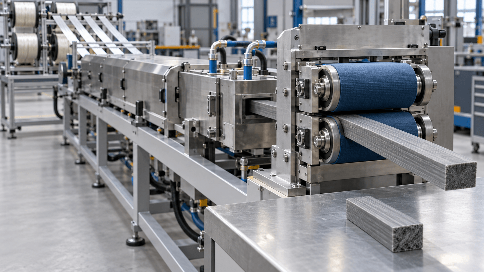
A published industrial example from Technoform feeds thermoplastic melt from an extruder into the pultrusion tool while continuous reinforcement passes through it. The formed profile is cooled before downstream pulling and cutting. Melt viscosity makes fiber impregnation a central design challenge; selecting a polymer does not establish that a particular tool will distribute it adequately. [1]
Prepared feedstock
Prepared feedstock moves some matrix distribution upstream, but the forms are not equivalent. Pre-impregnated tapes already contain an impregnated reinforcement structure. Commingled yarns combine polymer and reinforcing filaments, while powder-containing towpregs place polymer close to the reinforcement; these still need appropriate processing to develop impregnation and consolidation. [2]
Impregnation within an incoming tape does not, on its own, establish the quality of the section formed by consolidating multiple tapes. In a laboratory study of glass/polypropylene tapes, Tucci and colleagues used separate heating/forming and cooling dies. The finished section still showed nonuniform fiber distribution and matrix-rich regions. These observations explain why final-section inspection remains necessary even with pre-impregnated feedstock; they do not mean every tape-based profile develops the same defects. [2, Section 3 and Figure 5]
Reactive thermoplastic pultrusion
CQFD describes a route in which activated caprolactam forms PA6 around the reinforcement inside the die. The low-viscosity starting material assists impregnation, while polymer formation introduces chemistry-specific controls. CQFD identifies humidity and oxygen sensitivity for its described reaction. Those requirements must be checked for the actual formulation, not generalized to every thermoplastic process. [3]
Calling this route “thermoplastic” does not mean that it uses a conventional melt-fed setup. Equipment discussions should identify the route explicitly.
Why heating, consolidation, and cooling must be considered together
For a prepared-feedstock route, heating enables matrix flow and consolidation; cooling establishes a sufficiently stable profile. Pulling resistance can include compaction, viscous drag, and friction against solidified material. A force change alone therefore cannot identify which part of the process needs adjustment. [2]
A die-temperature setpoint alone does not describe the temperature history throughout the moving material. The cited glass/polypropylene study measured temperature inside the advancing composite alongside pulling force, rather than treating the equipment setting as the material temperature. Link the process record to the resulting profile: holding its external shape does not by itself establish adequate internal consolidation. [2, Sections 2–3]
As an engineering review framework, ask for:
- Feedstock identification: the polymer, reinforcement, incoming form, and material lot used in the trial.
- A linked process record: pulling speed, heating and cooling settings, available material-temperature measurements, and force observations tied to the sampled profile. Keep measured material temperatures distinct from equipment setpoints.
- Cross-section evidence: dimensions and reinforcement distribution, including matrix-rich regions and voids where relevant to the agreed inspection requirements.
- An application check: testing appropriate to the intended loading, joining, and service conditions.
This is a way to organize qualification evidence, not a substitute for a material supplier’s processing instructions or an approved acceptance specification. A visually smooth surface alone should not be the acceptance decision.
Where thermoplastic profiles can add value
Thermoplastic profiles can be useful when the downstream assembly benefits from compatible welding or overmolding operations. Ensinger describes both approaches for continuous-fiber thermoplastic profiles. Such possibilities are application-specific: the selected matrix, reinforcement arrangement, joint design, and subsequent process still need to work together. [4]
Start with the operation the finished profile must support. For an overmolded reinforcement insert, for example, the planning question is not merely whether the feedstock is thermoplastic. It is whether the proposed insert and molding process can meet the assembly’s requirements. For a welded assembly, include the joint in qualification rather than accepting profile properties as proof of joint performance.
Glass or carbon reinforcement is a separate choice from the matrix-processing route. Our carbon fiber pultrusion guide covers the reinforcement-specific topic; it should not be read as evidence that every carbon-fiber profile uses a thermoplastic matrix.
thermoplastic pultrusion
Remelting is a possibility, not a recycling plan
A thermoplastic matrix may permit thermal reprocessing, but an actual recovery route also needs suitable collection and processing arrangements. Ensinger explicitly makes this distinction. Do not translate “thermoplastic” into a guaranteed closed-loop recycling claim. [4]
For a project review, ask what material will be collected, who will process it, what output is expected, and where that output can be used. Require evidence for the proposed recovery route before making a product-level environmental claim. This avoids presenting a material characteristic as an operating recycling service.
What to resolve before a tooling inquiry
Prepare a short brief that identifies the proposed route and the decisions still open:
- Profile and function: cross-section drawing, critical dimensions, and intended application.
- Material and incoming form: matrix, reinforcement, and whether the feed is dry fiber, prepared feedstock, or a reactive system.
- Process interfaces: where impregnation, heating, consolidation, and cooling are intended to occur.
- Acceptance: which profile and assembly characteristics must be demonstrated, and what evidence will establish acceptance.
If the route is unresolved, record it as an open choice rather than requesting a die against an assumed process. That distinction helps prevent a tooling discussion from starting with incompatible inputs.
For an FRP tooling inquiry, visit our pultrusion molds and tooling page, or send us your drawing and application requirements. If your proposal involves a thermoplastic route, identify it explicitly and ask whether the requested tooling falls within our supply scope.
References
- Technoform — Thermoplastic pultrusion for composite profiles.
- Tucci, F.; Rubino, F.; Pasquino, G.; Carlone, P. — Thermoplastic Pultrusion Process of Polypropylene/Glass Tapes. Polymers 2023, 15, 2374. See Section 1 for feedstock forms, Section 2 and Figure 1 for the experimental setup, and Section 3 and Figure 5 for cross-section observations.
- CQFD Composites — Reactive thermoplastic pultrusion.
- Ensinger — Thermoplastic pultrusion.


